Vision 90t/100t Color Gamut Adjustment
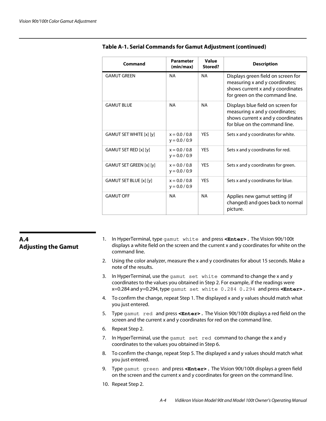
Table A-1. Serial Commands for Gamut Adjustment (continued)
Command | Parameter | Value | Description | |
(min/max) | Stored? | |||
|
| |||
|
|
|
| |
GAMUT GREEN | NA | NA | Displays green field on screen for | |
|
|
| measuring x and y coordinates; | |
|
|
| shows current x and y coordinates | |
|
|
| for green on the command line. | |
|
|
|
| |
GAMUT BLUE | NA | NA | Displays blue field on screen for | |
|
|
| measuring x and y coordinates; | |
|
|
| shows current x and y coordinates | |
|
|
| for blue on the command line. | |
|
|
|
| |
GAMUT SET WHITE [x] [y] | x = 0.0 / 0.8 | YES | Sets x and y coordinates for white. | |
| y = 0.0 / 0.9 |
|
| |
|
|
|
| |
GAMUT SET RED [x] [y] | x = 0.0 / 0.8 | YES | Sets x and y coordinates for red. | |
| y = 0.0 / 0.9 |
|
| |
|
|
|
| |
GAMUT SET GREEN [x] [y] | x = 0.0 / 0.8 | YES | Sets x and y coordinates for green. | |
| y = 0.0 / 0.9 |
|
| |
|
|
|
| |
GAMUT SET BLUE [x] [y] | x = 0.0 / 0.8 | YES | Sets x and y coordinates for blue. | |
| y = 0.0 / 0.9 |
|
| |
|
|
|
| |
GAMUT OFF | NA | NA | Applies new gamut setting (if | |
|
|
| changed) and goes back to normal | |
|
|
| picture. | |
|
|
|
|
A.4
Adjusting the Gamut
1.In HyperTerminal, type gamut white and press <Enter>. The Vision 90t/100t displays a white field on the screen and the current x and y coordinates for white on the command line.
2.Using the color analyzer, measure the x and y coordinates for about 15 seconds. Make a note of the results.
3.In HyperTerminal, use the gamut set white command to change the x and y coordinates to the values you obtained in Step 2. For example, if the readings were x=0.284 and y=0.294, type gamut set white 0.284 0.294 and press <Enter>.
4.To confirm the change, repeat Step 1. The displayed x and y values should match what you just entered.
5.Type gamut red and press <Enter>. The Vision 90t/100t displays a red field on the screen and the current x and y coordinates for red on the command line.
6.Repeat Step 2.
7.In HyperTerminal, use the gamut set red command to change the x and y coordinates to the values you obtained in Step 6.
8.To confirm the change, repeat Step 5. The displayed x and y values should match what you just entered.
9.Type gamut green and press <Enter>. The Vision 90t/100t displays a green field on the screen and the current x and y coordinates for green on the command line.
10.Repeat Step 2.