Installation
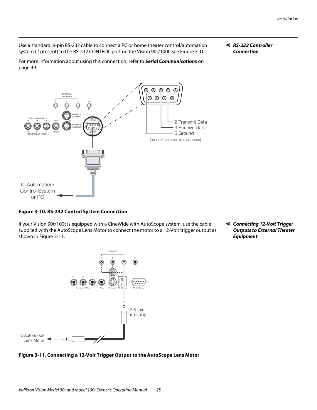
Use a standard, | |
system (if present) to the | Connection |
For more information about using this connection, refer to Serial Communications on |
|
page 49. |
|
|
|
|
| TRIGGERS |
|
|
|
|
|
| TRIGGERS |
|
|
|
|
| 1 | 2 | 3 | IR |
|
|
| 1 | 2 | 3 | IR |
|
|
|
|
| 1 |
|
VIDEO COMPONENT |
|
| CONTROL | |||
|
|
| ||||
Pb | Pr | Y | VIDEO |
|
| |
|
|
|
|
| 2 |
|
|
|
|
|
|
| |
Pb | Pr | Y | VIDEO |
|
| |
COMPONENT VIDEO |
|
|
| CONTROL | ||
5 4 3 2 1
9 8 7 6
2 Transmit Data
3 Receive Data
5 Ground
(none of the other pins are used)
to Automation/ Control System or PC
Figure 3-10. RS-232 Control System Connection
If your Vision 90t/100t is equipped with a CineWide with AutoScope system, use the cable supplied with the AutoScope Lens Motor to connect the motor to a
TRIGGERS
1 | 2 | 3 | IR |
![]() Connecting
Connecting
Outputs to External Theater
Equipment
Pb | Pr | Y |
|
|
| |
| Component Video |
| Video |
to AutoScope Lens Motor ![]()
![]()
Figure 3-11. Connecting a 12-Volt Trigger Output to the AutoScope Lens Motor
Vidikron Vision Model 90t and Model 100t Owner’s Operating Manual | 25 |