| INPUTS | INPUTS |
|
|
|
|
|
|
|
R | G | B |
|
|
|
|
|
|
|
Pr | Y | Pb | H | V |
|
|
|
|
|
|
|
|
|
|
|
|
| TRIGGERS |
|
|
|
|
|
| HD1 |
|
| TRIGGERS |
|
|
|
|
|
| HD1 |
|
|
|
|
|
|
|
|
|
|
| 1 | 2 | 3 |
|
|
|
|
| HD2 |
| 1 | 2 | 3 |
|
|
|
|
| HD2 |
| |||
R | G | B | H | V |
|
|
|
| 1 |
Pr | Y | Pb |
| VIDEO COMPONENT |
|
| |||
|
|
|
| VIDEO |
|
| |||
1 DVI |
| 2 DVI |
| Pb | Pr | Y |
|
| |
|
|
|
|
|
|
|
| ||
2 |
DVI 1 | DVI 2 | Pb |
| Pr | Y |
|
| VIDEO |
|
|
| ||||||
|
| COMPONENT VIDEO |
|
|
|
|
|
|
| ||||||||
|
|
|
|
|
|
|
|
|
|
|
|
|
|
|
|
|
|
|
|
|
|
|
|
|
|
|
|
|
|
|
|
|
|
|
|
|
|
|
|
|
|
|
|
|
|
|
|
|
|
|
|
|
|
|
|
|
|
|
|
|
|
|
|
|
|
|
|
|
|
|
|
|
|
|
|
|
|
|
|
|
|
|
|
|
|
|
|
|
|
|
|
|
|
|
|
|
|
|
|
|
|
|
|
|
|
|
|
|
|
|
|
|
|
|
|
|
|
|
|
|
|
|
|
|
|
|
|
|
|
|
|
|
|
|
|
|
|
|
|
|
|
|
|
|
|
|
|
|
|
|
|
|
|
|
|
|
|
|
|
|
|
|
|
|
|
|
|
|
|
|
|
|
|
|
|
|
|
|
|
|
|
|
|
|
|
|
|
|
|
|
|
|
|
|
|
|
|
|
|
|
|
|
|
|
|
|
|
|
|
|
|
|
|
|
|
|
|
|
|
|
|
|
|
|
|
|
|
|
|
|
|
|
|
|
|
|
|
|
|
|
|
|
|
|
|
|
|
|
|
|
|
IR
IR
CONTROL
CONTROL
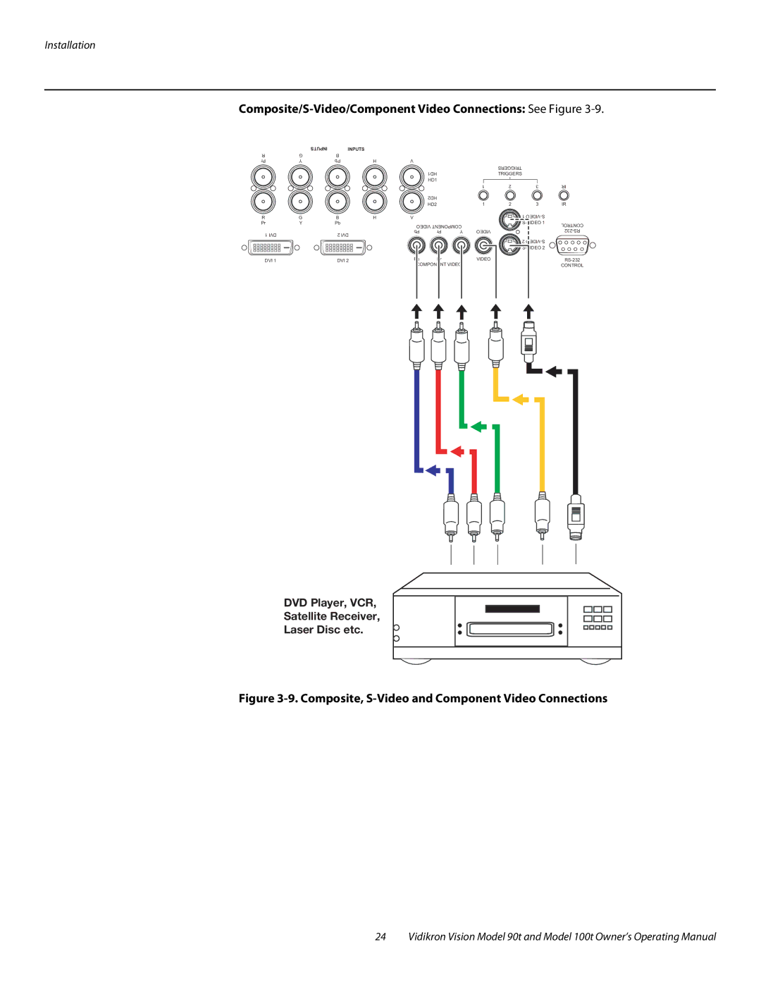
DVD Player, VCR,
Satellite Receiver,
Laser Disc etc.
Figure 3-9. Composite, S-Video and Component Video Connections
24 Vidikron Vision Model 90t and Model 100t Owner’s Operating Manual