Vision 90t/100t Color Gamut Adjustment
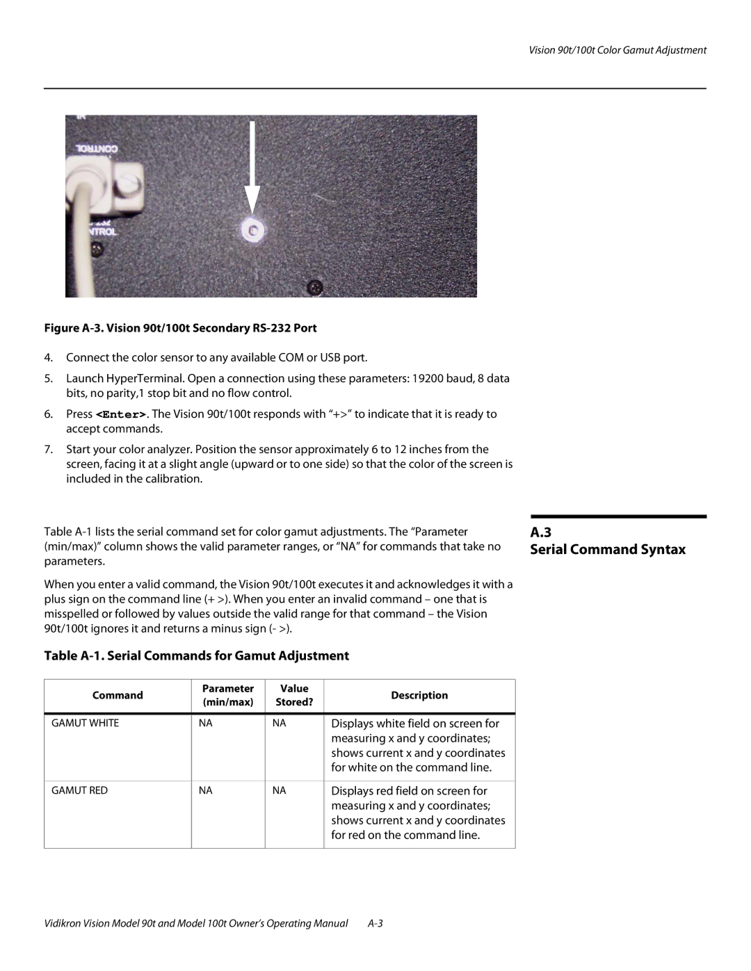
Figure A-3. Vision 90t/100t Secondary RS-232 Port
4.Connect the color sensor to any available COM or USB port.
5.Launch HyperTerminal. Open a connection using these parameters: 19200 baud, 8 data bits, no parity,1 stop bit and no flow control.
6.Press <Enter>. The Vision 90t/100t responds with “+>” to indicate that it is ready to accept commands.
7.Start your color analyzer. Position the sensor approximately 6 to 12 inches from the screen, facing it at a slight angle (upward or to one side) so that the color of the screen is included in the calibration.
Table
When you enter a valid command, the Vision 90t/100t executes it and acknowledges it with a plus sign on the command line (+ >). When you enter an invalid command – one that is misspelled or followed by values outside the valid range for that command – the Vision 90t/100t ignores it and returns a minus sign (- >).
Table A-1. Serial Commands for Gamut Adjustment
Command | Parameter | Value | Description | |
(min/max) | Stored? | |||
|
| |||
|
|
|
| |
GAMUT WHITE | NA | NA | Displays white field on screen for | |
|
|
| measuring x and y coordinates; | |
|
|
| shows current x and y coordinates | |
|
|
| for white on the command line. | |
|
|
|
| |
GAMUT RED | NA | NA | Displays red field on screen for | |
|
|
| measuring x and y coordinates; | |
|
|
| shows current x and y coordinates | |
|
|
| for red on the command line. | |
|
|
|
|
A.3
Serial Command Syntax
Vidikron Vision Model 90t and Model 100t Owner’s Operating Manual |
