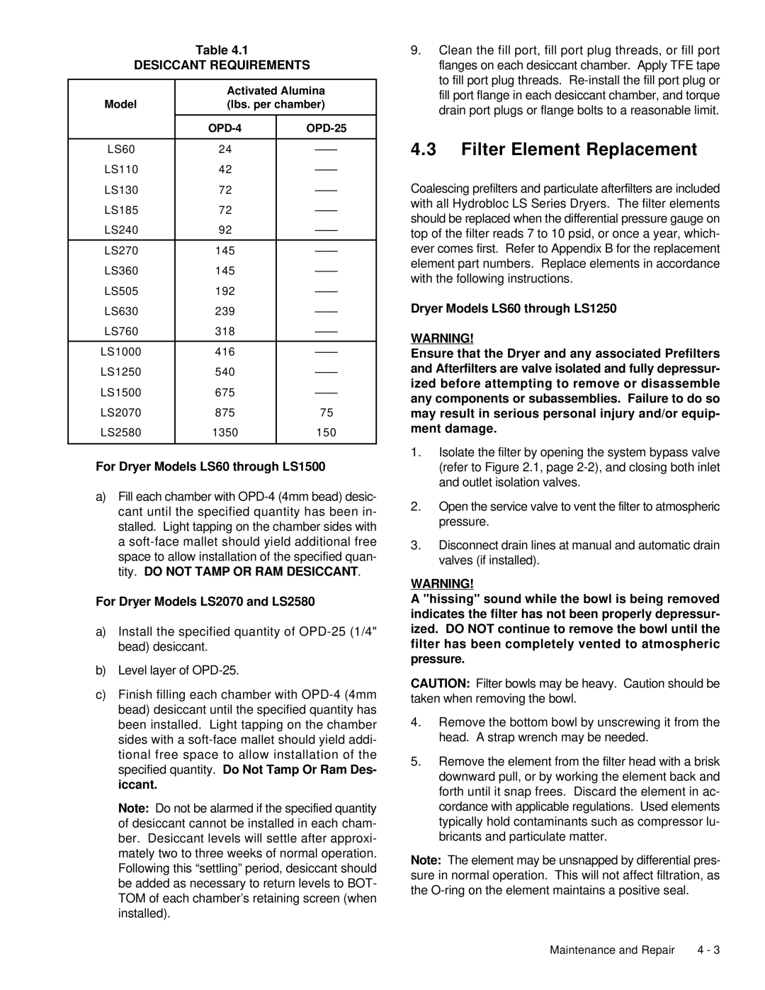
LS60, LS2580 specifications
Deltech Fitness is renowned for providing high-quality strength training equipment, and their LS2580 and LS60 models are no exception. Both of these machines have been designed with the serious fitness enthusiast in mind, offering a range of features that cater to effective strength training routines.The LS2580 is a multi-station home gym designed to facilitate a variety of exercises without needing multiple machines. This versatility allows users to perform a full-body workout in the comfort of their own home. One of the main features of the LS2580 is its adjustable weight stack, which provides users with the flexibility to customize their workouts. It boasts a robust and stable frame, engineered to withstand the demands of heavy usage.
With a focus on user safety, the LS2580 incorporates several safety features, including easily accessible adjustment points and non-slip grips. This makes switching between exercises seamless and reduces the risk of injury. The machine also supports a range of movements including lat pulldowns, leg presses, chest presses, and more, allowing users to target different muscle groups effectively.
On the other hand, the Deltech Fitness LS60 is a slightly simpler yet equally impressive machine that excels in offering a compact solution for strength training. The LS60 focuses on essential muscle groups, catering to those who may have limited space but do not want to compromise on their workout regimen. It is designed with a sturdy frame and is ideal for users who prioritize stability and durability in their fitness equipment.
One of the standout features of the LS60 is its adjustable seat height, making it suitable for various body types. This adaptability ensures that everyone can maintain proper form during workouts, which is crucial for both performance and safety. The LS60 also comes with various attachment points, allowing users to incorporate resistance bands or other accessories to enhance their training.
In terms of technology, both the LS2580 and LS60 emphasize user-friendly design elements that promote an intuitive workout experience. The clear labeling of each exercise station makes transitioning between workouts simple and efficient.
In summary, both Deltech Fitness LS2580 and LS60 present compelling options for fitness enthusiasts, providing a versatile and effective solution for strength training. Whether you opt for the comprehensive features of the LS2580 or the compact design of the LS60, you can expect durability, safety, and a focus on achieving your fitness goals at home.
