PRE-INSTALLATION
PREPARATION
Continued
VENT TERMINATION CLEARANCES
The final position of your fireplace depends on the location of the vent termination in relation to the clearances that must be observed as shown in Figure 5 on page 6.
The vent system serves as the “chimney” as well as the combustion air supply (air intake). The horizontal run must have a rise of 1/4" (.6 cm) for every 12" (30.48 cm) of horizontal run towards the termination. The maximum horizontal run depends on the vertical rise from the fireplace adapter collar to the vent termination (see table below).
VERTICAL |
| HORIZONTAL |
|
|
|
0 | to | 1 ft (30.48 cm) |
1 ft (30.48 cm) | to | 4 ft (121.92 cm) |
2 ft (60.96 cm) | to | 8 ft (243.84 cm) |
3 ft (91.44 cm) | to | 12 ft (365.76 cm) |
4 ft (121.92 cm) | to | 16 ft (487.68 cm) |
5 ft (152.40 cm) | to | 15 ft (457.20 cm) |
6 ft (182.88 cm) | to | 14 ft (426.72 cm) |
7 ft (213.36 cm) | to | 13 ft (396.24 cm) |
8 ft (243.84 cm) | to | 12 ft (365.76 cm) |
|
|
|
![]() WARNING: Never allow the vent to run downward as this may cause excessive tempera- tures which could cause a fire.
WARNING: Never allow the vent to run downward as this may cause excessive tempera- tures which could cause a fire.
![]() WARNING: Horizontal sec- tions of this vent system require a minimum clearance of 2" from the top of the pipe and 1" mini- mum to the sides and bottom. Vertical sections of this system require a minimum of 1" clear- ance to combustible materials on all sides of the pipe.
WARNING: Horizontal sec- tions of this vent system require a minimum clearance of 2" from the top of the pipe and 1" mini- mum to the sides and bottom. Vertical sections of this system require a minimum of 1" clear- ance to combustible materials on all sides of the pipe.
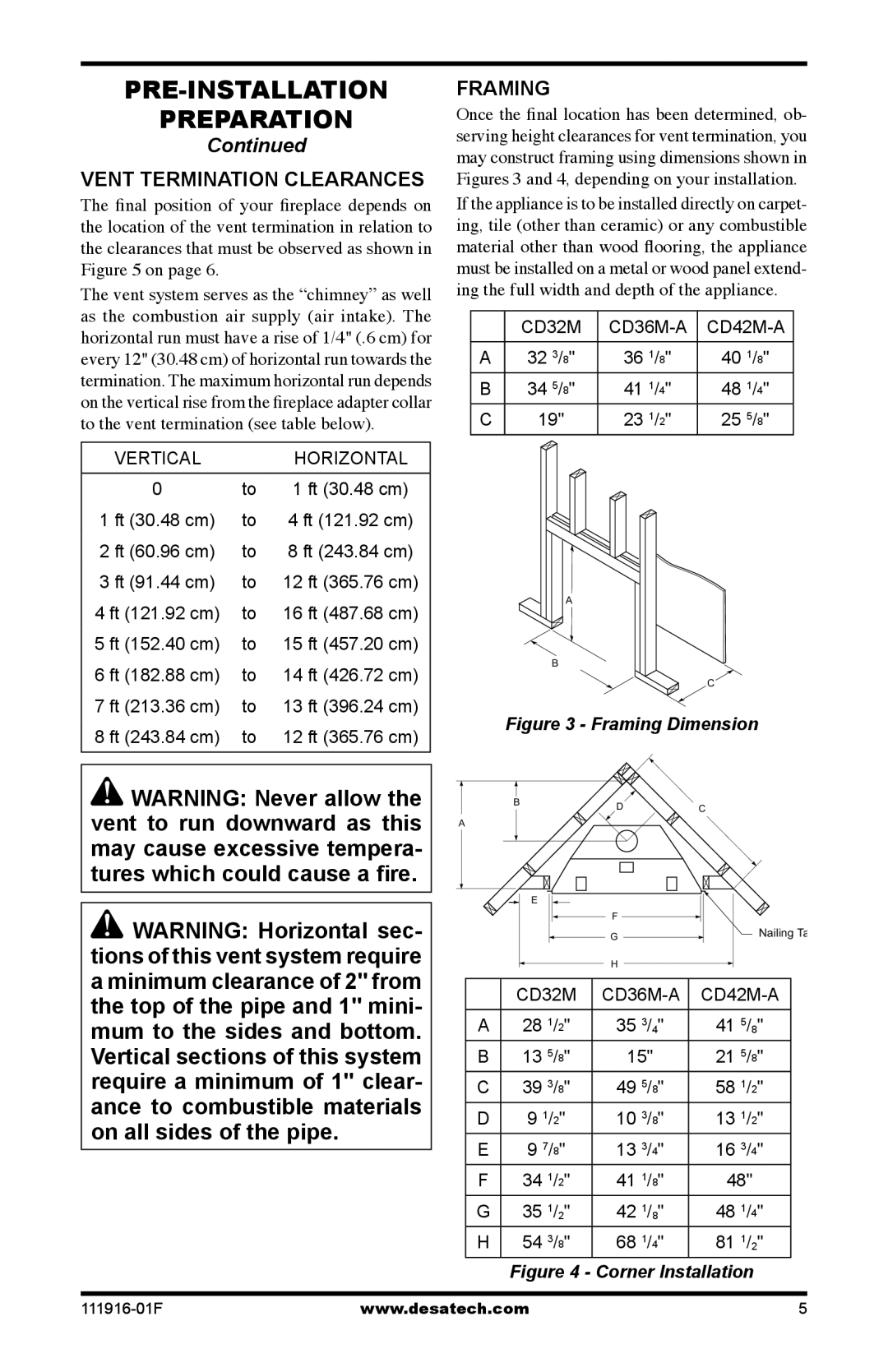
FRAMING
Once the final location has been determined, ob- serving height clearances for vent termination, you may construct framing using dimensions shown in Figures 3 and 4, depending on your installation.
If the appliance is to be installed directly on carpet- ing, tile (other than ceramic) or any combustible material other than wood flooring, the appliance must be installed on a metal or wood panel extend- ing the full width and depth of the appliance.
| CD32M | ||
|
|
|
|
A | 32 3/8" | 36 1/8" | 40 1/8" |
B | 34 5/8" | 41 1/4" | 48 1/4" |
C | 19" | 23 1/2" | 25 5/8" |
A
B
C
Figure 3 - Framing Dimension
BDC
A
E |
|
F |
|
G | Nailing Ta |
| |
H |
|
| CD32M | ||||||||||
|
|
|
|
|
|
|
|
|
| ||
A | 28 | 1 | / " | 35 | 3 | /4" | 41 | 5 | /8" | ||
|
| 2 |
|
|
|
|
|
| |||
B | 13 | 5 | / " | 15" |
| 21 | 5 | / | " | ||
|
| 8 |
|
|
|
|
| 8 |
| ||
C | 39 | 3 | / " | 49 | 5 | / | " | 58 | 1 | / | " |
|
| 8 |
| 8 |
|
| 2 |
| |||
D | 9 1/2" | 10 3/8" | 13 1/2" | ||||||||
E | 9 7/8" | 13 3/4" | 16 3/4" | ||||||||
F | 34 | 1 | / " | 41 | 1 | / | " | 48" |
| ||
|
| 2 |
| 8 |
|
|
|
|
| ||
G | 35 1/2" | 42 1/8" | 48 1/4" | ||||||||
H | 54 | 3 | / " | 68 | 1 | / | " | 81 | 1 | /2" | |
|
| 8 |
| 4 |
|
|
|
| |||
Figure 4 - Corner Installation
www.desatech.com | 5 |