14
VENTING INSTALLATION
Installation For Horizontal Termination (Cont.)
VENTING INSTALLATION
Continued
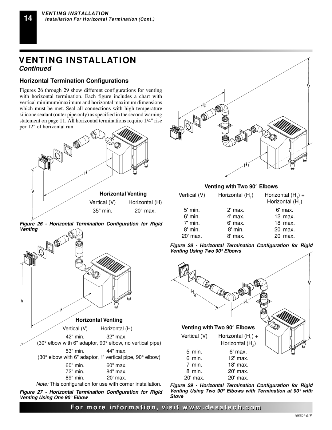
Horizontal Termination Configurations
Figures 26 through 29 show different configurations for venting with horizontal termination. Each figure includes a chart with vertical minimum/maximum and horizontal maximum dimensions which must be met. Seal all connections with high temperature silicone sealant (outer pipe only) as specified in the second warning statement on page 11. All horizontal terminations require 1/4" rise per 12" of horizontal run.
Horizontal Venting
Vertical (V) | Horizontal (H) |
35" min. | 20" max. |
Figure 26 - Horizontal Termination Configuration for Rigid Venting

Horizontal Venting
Vertical (V) | Horizontal (H) |
42" min. | 32" max. |
(30° elbow with 6" adaptor, 90° elbow, no vertical pipe)
53" min. 44" max.
(30° elbow with 6" adaptor, 1' vertical pipe, 90° elbow)
60" min. | 60" max. |
72" min. | 84" max. |
89" min. | 20' max. |
Note: This configuration for use with corner installation.
Figure 27 - Horizontal Termination Configuration for Rigid Venting Using One 90° Elbow
Venting with Two 90° Elbows
Vertical (V) | Horizontal (H1) | Horizontal (H1) + |
|
| Horizontal (H2) |
5' min. | 2' max. | 6' max. |
6' min. | 4' max. | 12' max. |
7' min. | 6' max. | 18' max. |
8' min. | 8' min. | 20' max. |
20' max. | 8' max. | 20' max. |
Figure 28 - Horizontal Termination Configuration for Rigid Venting Using Two 90° Elbows
Venting with Two 90° Elbows
Vertical (V) | Horizontal (H1) + |
| Horizontal (H2) |
5' min. | 6' max. |
6' min. | 12' max. |
7' min. | 18' max. |
8' min. | 20' max. |
20' max. | 20' max. |
Figure 29 - Horizontal Termination Configuration for Rigid Venting Using Two 90° Elbows with Termination at 90° with Stove
![]()
![]()
![]()
![]()
![]() For
For![]()
![]()
![]()
![]()
![]()
![]()
![]()
![]()
![]()
![]()
![]()
![]()
![]() .
.![]()
![]()
![]()
![]() .com
.com![]()
![]()
![]()
![]()
![]()