INSTALLATION
Installing Thermostatic Blower Accessory (Cont.) Installing Gas Piping to Fireplace Location
15
INSTALLATION
Continued
15.If gas connections have been made and checked, replace fireplace floor assembly in fireplace. Feed flexible gas supply line into fire- place base area while replacing fireplace floor assembly. Make sure the entire flexible gas line is in fireplace base area. IMPORTANT: Do not pick up fireplace floor assembly by burners. This could damage burners. Only handle base by grates. Note: Be careful of all wires and components on underside of floor assembly.
16.Reattach fireplace floor assembly with screws removed in step 3 of Removing Fireplace Screen and Floor Assembly, page 8.
Note: Discard the remaining hardware items. After assembly, make sure all wires are completely clear of blower wheel.
17.Install logs (see Installing Logs, pages 21 through 23) and fire- place screen (see Installing Screen, page 24).
![]() WARNING: Failure to position the parts in accor- dance with supplied diagrams or failure to use only parts specifically approved with this heater may result in damage or personal injury.
WARNING: Failure to position the parts in accor- dance with supplied diagrams or failure to use only parts specifically approved with this heater may result in damage or personal injury.
![]() WARNING: A qualified service person must con- nect fireplace to gas supply. Follow all local codes.
WARNING: A qualified service person must con- nect fireplace to gas supply. Follow all local codes.
If any of the original wire as supplied with the appliance must be replaced, it must be replaced with 105˚C wire or it's equivalent.
Operating the Blower
After final installation of your fireplace, light your gas appliance with the blower off. After about 15 minutes, turn the blower on to deliver heated air at the top louvers. The blower features a variable control which allows you to select the speed you desire. In the OFF position, the blower will not operate. In the ON position, the blower will start when the thermostat senses a sufficient increase in firebox temperature (approximately 10 to 20 minutes depend- ing on heat setting).
Your gas logs and thermostat blower will not turn on and off at the same time. The fireplace may run for several minutes before the blower turns on. After the heater modulates to the pilot position, the blower will continue to run. The blower will shut off after the firebox temperature decreases.
It is safe to operate fireplace with blower turned off. However, the blower helps distribute heated air from the fireplace.
Note: Periodically check the louvers of the firebox and remove any dust, dirt, or other obstructions.
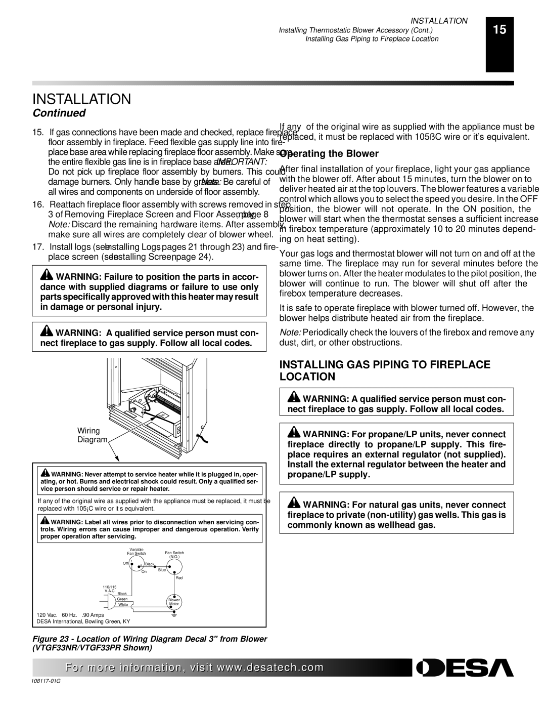
Wiring
Diagram
![]() WARNING: Never attempt to service heater while it is plugged in, oper- ating, or hot. Burns and electrical shock could result. Only a qualified ser- vice person should service or repair heater.
WARNING: Never attempt to service heater while it is plugged in, oper- ating, or hot. Burns and electrical shock could result. Only a qualified ser- vice person should service or repair heater.
If any of the original wire as supplied with the appliance must be replaced, it must be replaced with 105°C wire or it’s equivalent.
![]() WARNING: Label all wires prior to disconnection when servicing con- trols. Wiring errors can cause improper and dangerous operation. Verify proper operation after servicing.
WARNING: Label all wires prior to disconnection when servicing con- trols. Wiring errors can cause improper and dangerous operation. Verify proper operation after servicing.
Variable
Fan SwitchFan Switch
(N.O.)
Off 1 | 2 Black |
|
| On | Blue |
|
|
Red
110/115
V.A.C.
Black
Green | Blower |
White | Motor |
120 Vac. 60 Hz. .90 Amps
DESA International, Bowling Green, KY
Figure 23 - Location of Wiring Diagram Decal 3" from Blower (VTGF33NR/VTGF33PR Shown)
INSTALLING GAS PIPING TO FIREPLACE LOCATION
![]() WARNING: A qualified service person must con- nect fireplace to gas supply. Follow all local codes.
WARNING: A qualified service person must con- nect fireplace to gas supply. Follow all local codes.
![]() WARNING: For propane/LP units, never connect fireplace directly to propane/LP supply. This fire- place requires an external regulator (not supplied). Install the external regulator between the heater and propane/LP supply.
WARNING: For propane/LP units, never connect fireplace directly to propane/LP supply. This fire- place requires an external regulator (not supplied). Install the external regulator between the heater and propane/LP supply.
![]() WARNING: For natural gas units, never connect fireplace to private
WARNING: For natural gas units, never connect fireplace to private
![]() For more
For more![]()
![]()
![]() visit www.
visit www.![]()
![]()
![]() .com
.com![]()
![]()
![]()
![]()
![]()
![]()