INSTALLATION
Installing Variable Speed Blower Accessory (Cont.) Installing Thermostatic Blower Accessory
13
INSTALLATION
Continued
Wiring
Diagram 
![]() WARNING: Never attempt to service heater while it is plugged in, oper- ating, or hot. Burns and electrical shock could result. Only a qualified ser- vice person should service or repair heater.
WARNING: Never attempt to service heater while it is plugged in, oper- ating, or hot. Burns and electrical shock could result. Only a qualified ser- vice person should service or repair heater.
If any of the original wire as supplied with the appliance must be replaced, it must be replaced with 105°C wire or it’s equivalent.
![]() WARNING: Label all wires prior to disconnection when servicing con- trols.Wiring errors can cause improper and dangerous operation.Verify proper operation after servicing.
WARNING: Label all wires prior to disconnection when servicing con- trols.Wiring errors can cause improper and dangerous operation.Verify proper operation after servicing.
Variable
|
|
|
| Fan Switch | |||||||||
|
|
|
|
|
|
|
|
|
|
|
|
|
|
|
|
|
| Off | Black | On | |||||||
110/115 | Black |
| Blower | ||||||||||
|
| V.A.C. |
|
|
|
| Motor | ||||||
|
|
| Black |
|
|
|
| Black | |||||
|
|
| Green |
|
|
|
|
|
|
|
|
|
|
|
|
| White |
|
|
|
| White | |||||
120 Vac. 60 Hz. . 78 Amps |
|
|
|
|
|
|
|
|
|
| |||
|
|
|
|
|
|
|
|
|
| ||||
|
|
| |||||||||||
DESA International, Bowling Green, KY | |||||||||||||
Figure 17 - Location of Wiring Diagram Decal 3" from Blower (VTGF33NR/VTGF33PR Shown)
Operating the Blower
Light your gas appliance with the blower off. After about 15 minutes, turn the blower on to deliver heated air at the top louvers. The blower features a variable control which allows you to select the speed you desire. Note: Periodically check the louvers of the fire- box and remove any dust, dirt, or other obstructions.
INSTALLING THERMOSTATIC BLOWER ACCESSORY
NOTICE: Shut off gas supply and disconnect heater from gas supply if installing blower in previously installed fireplace. Contact a qualified service person to do this.
1.If fireplace screen and floor are still installed, see Removing
Fireplace Screen and Floor Assembly, page 8.
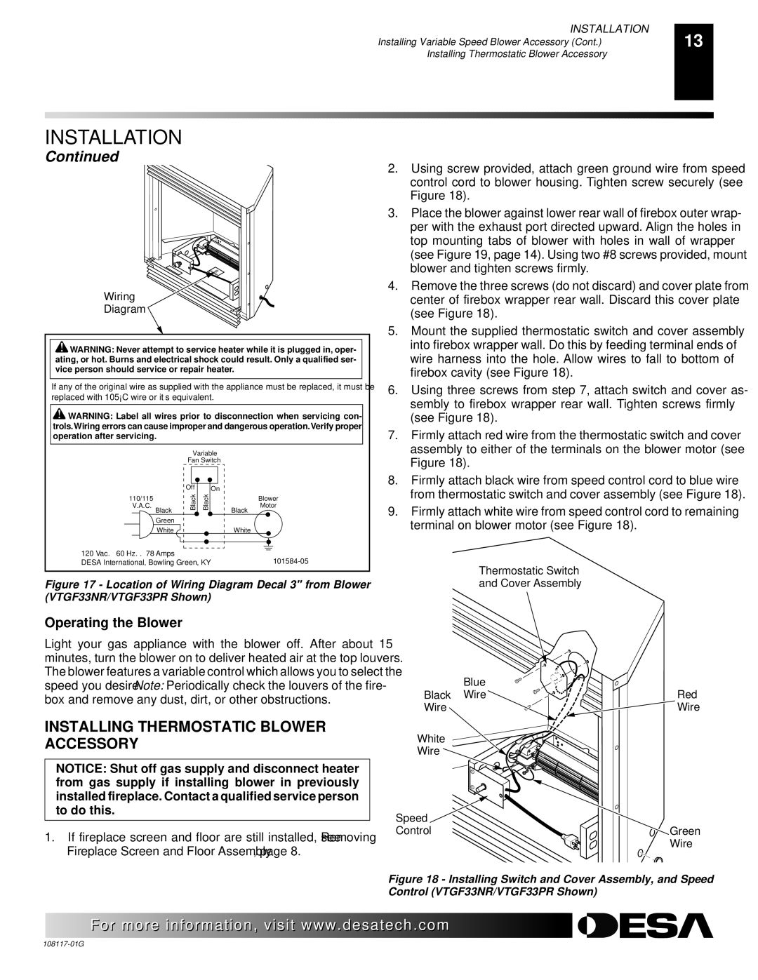
2.Using screw provided, attach green ground wire from speed control cord to blower housing. Tighten screw securely (see Figure 18).
3.Place the blower against lower rear wall of firebox outer wrap- per with the exhaust port directed upward. Align the holes in top mounting tabs of blower with holes in wall of wrapper (see Figure 19, page 14). Using two #8 screws provided, mount blower and tighten screws firmly.
4.Remove the three screws (do not discard) and cover plate from center of firebox wrapper rear wall. Discard this cover plate (see Figure 18).
5.Mount the supplied thermostatic switch and cover assembly into firebox wrapper wall. Do this by feeding terminal ends of wire harness into the hole. Allow wires to fall to bottom of firebox cavity (see Figure 18).
6.Using three screws from step 7, attach switch and cover as- sembly to firebox wrapper rear wall. Tighten screws firmly (see Figure 18).
7.Firmly attach red wire from the thermostatic switch and cover assembly to either of the terminals on the blower motor (see Figure 18).
8.Firmly attach black wire from speed control cord to blue wire from thermostatic switch and cover assembly (see Figure 18).
9.Firmly attach white wire from speed control cord to remaining terminal on blower motor (see Figure 18).
Thermostatic Switch
and Cover Assembly
Blue |
|
Black Wire | Red |
Wire | Wire |
White |
|
Wire |
|
Speed |
|
Control | Green |
| Wire |
Figure 18 - Installing Switch and Cover Assembly, and Speed Control (VTGF33NR/VTGF33PR Shown)
![]() For more
For more![]()
![]()
![]() visit www.
visit www.![]()
![]()
![]() .com
.com![]()
![]()
![]()
![]()
![]()
![]()