OWNER’S MANUAL
VENTING INSTALLATION
Continued
3.Lower the support box through the hole in the roof until the bottom of the box extends at least 2" below the ceiling (see Figure 23). Align the support box vertically and horizontally using a level. Temporarily tack the support box in place through the inside walls and into the roof sheathing.
4.Using tin snips, cut the support box from the top corners down to the roofline and fold the resulting flaps over the roof sheathing (see Figure 24). Apply a bead of
5.Complete the cathedral ceiling instal- lation by following the same proce- dures outlined in steps 2 through 7 for Flat Ceiling Installation, page 12.
Level
Cathedral ceiling support box
2" minimum below finished ceiling
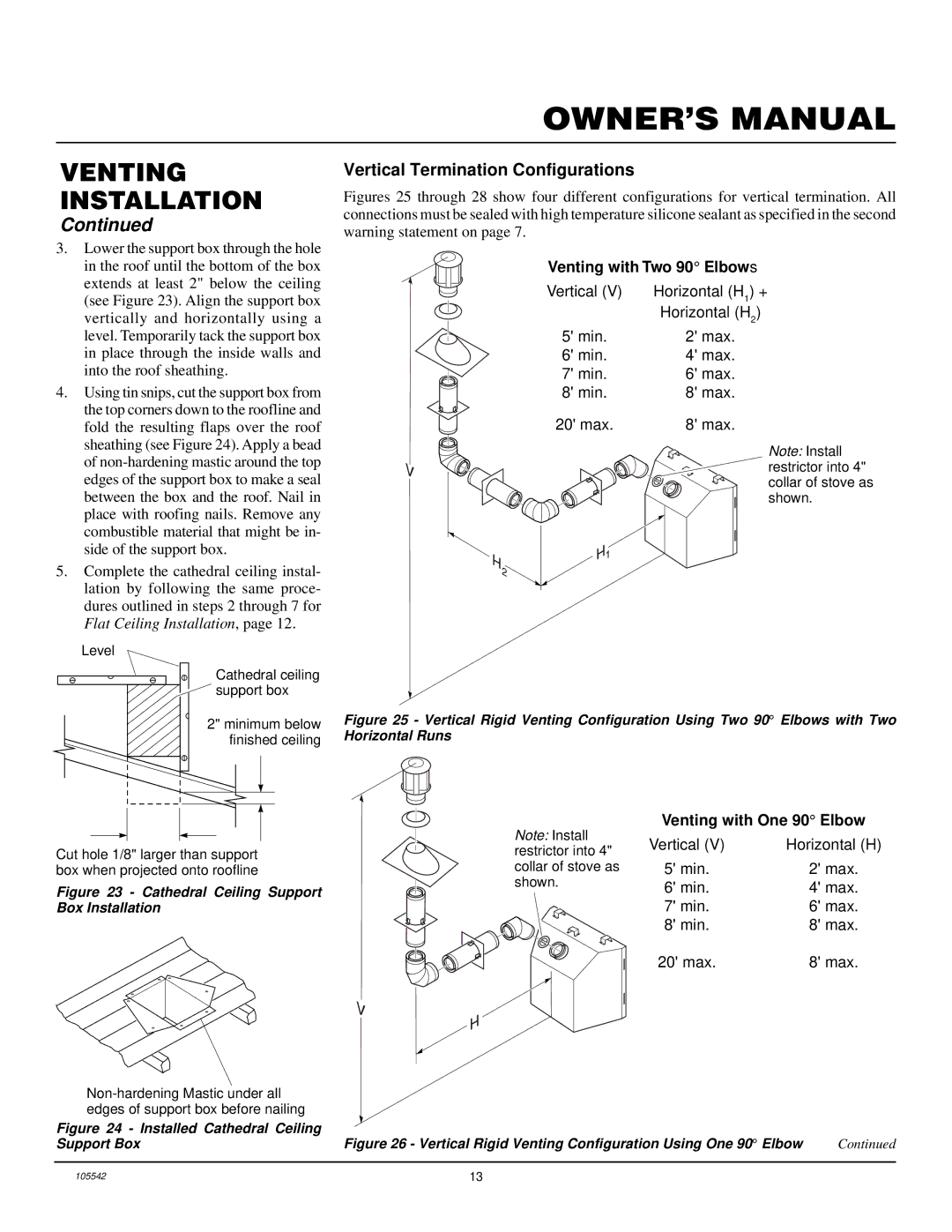
Vertical Termination Configurations
Figures 25 through 28 show four different configurations for vertical termination. All connections must be sealed with high temperature silicone sealant as specified in the second warning statement on page 7.
Venting with Two 90° Elbows
Vertical (V) | Horizontal (H1) + |
| Horizontal (H2) |
5' min. | 2' max. |
6' min. | 4' max. |
7' min. | 6' max. |
8' min. | 8' max. |
20' max. | 8' max. |
Note: Install restrictor into 4" collar of stove as shown.
Figure 25 - Vertical Rigid Venting Configuration Using Two 90° Elbows with Two
Horizontal Runs
Cut hole 1/8" larger than support box when projected onto roofline
Figure 23 - Cathedral Ceiling Support Box Installation
Venting with One 90° Elbow
Note: Install | Vertical (V) | Horizontal (H) | |
restrictor into 4" | |||
|
| ||
collar of stove as | 5' min. | 2' max. | |
shown. | 6' min. | 4' max. | |
| |||
| 7' min. | 6' max. | |
| 8' min. | 8' max. | |
| 20' max. | 8' max. |
Figure 24 - Installed Cathedral Ceiling | Figure 26 - Vertical Rigid Venting Configuration Using One 90° Elbow |
|
Support Box | Continued |
105542 | 13 |