OWNER’S MANUAL
PRE-INSTALLATION PREPARATION
Continued
GENERAL VENTING
These models are approved for use with Simpson
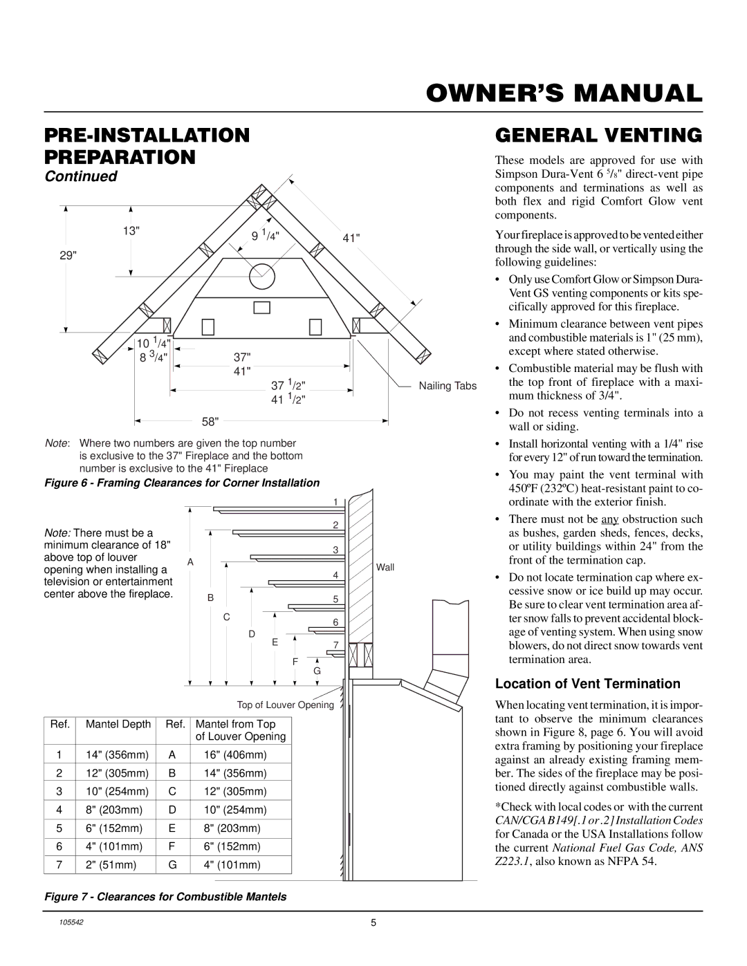
13" |
|
| 9 1/4" |
| 41" |
|
|
| Your fireplace is approved to be vented either | |||||||
29" |
|
|
|
|
|
|
|
|
|
|
|
|
|
| through the side wall, or vertically using the | |
|
|
|
|
|
|
|
|
|
|
|
|
|
| following guidelines: | ||
|
|
|
|
|
|
|
|
|
|
|
|
|
|
| ||
|
|
|
|
|
|
|
|
|
|
|
|
|
|
| • Only use Comfort Glow or Simpson Dura- | |
|
|
|
|
|
|
|
|
|
|
|
|
|
|
|
| Vent GS venting components or kits spe- |
|
|
|
|
|
|
|
|
|
|
|
|
|
|
|
| cifically approved for this fireplace. |
|
|
|
|
|
|
|
|
|
|
|
|
|
|
| • Minimum clearance between vent pipes | |
|
|
|
|
|
|
|
|
|
|
|
|
|
|
| ||
| 10 1/4" |
|
|
|
|
|
|
|
|
|
|
|
|
|
| and combustible materials is 1" (25 mm), |
|
|
|
|
|
|
|
|
|
|
|
|
|
|
| ||
|
|
|
|
|
|
|
|
|
|
|
|
|
|
| ||
| 8 3/4" |
|
| 37" |
|
|
|
|
|
|
|
| except where stated otherwise. | |||
|
|
|
|
|
|
|
|
|
| • Combustible material may be flush with | ||||||
|
|
|
| 41" |
|
|
|
|
|
|
| |||||
|
|
|
|
|
|
|
|
|
|
| ||||||
|
|
|
| 37 | 1 | /2" |
|
|
|
|
| Nailing Tabs | the top front of fireplace with a maxi- | |||
|
|
|
|
|
|
|
|
|
| mum thickness of 3/4". | ||||||
|
|
|
| 41 1/2" |
|
|
|
|
|
| ||||||
|
|
|
|
|
|
|
|
| ||||||||
|
|
|
| 58" |
|
|
|
|
|
|
|
| • Do not recess venting terminals into a | |||
|
|
|
|
|
|
|
|
|
|
|
|
| wall or siding. | |||
|
|
|
|
|
|
|
|
|
|
|
|
| ||||
|
|
|
|
|
|
|
|
|
|
|
|
|
|
|
| |
Note: Where two numbers are given the top number |
|
| • Install horizontal venting with a 1/4" rise | |||||||||||||
is exclusive to the 37" Fireplace and the bottom |
|
|
| for every 12" of run toward the termination. | ||||||||||||
number is exclusive to the 41" Fireplace |
|
|
|
|
|
|
| • | You may paint the vent terminal with | |||||||
Figure 6 - Framing Clearances for Corner Installation |
|
| ||||||||||||||
|
|
| 450ºF (232ºC) | |||||||||||||
|
|
|
|
|
|
|
|
|
|
|
|
|
|
|
| |
|
|
|
|
|
|
|
|
| 1 |
|
|
|
|
|
| ordinate with the exterior finish. |
|
|
|
|
|
|
|
|
| 2 |
|
|
|
|
| • | There must not be any obstruction such |
Note: There must be a |
|
|
|
|
|
|
|
|
|
|
| as bushes, garden sheds, fences, decks, | ||||
|
|
|
|
|
|
|
|
|
|
|
| |||||
minimum clearance of 18" |
|
|
|
|
| 3 |
|
|
|
|
|
| or utility buildings within 24" from the | |||
above top of louver |
|
|
|
|
|
|
|
|
|
|
| front of the termination cap. | ||||
A |
|
|
|
|
|
| Wall | |||||||||
opening when installing a |
|
|
|
|
| 4 |
|
|
|
|
| |||||
television or entertainment |
|
|
|
|
|
|
|
|
|
| • Do not locate termination cap where ex- | |||||
|
|
|
|
|
|
|
|
|
|
|
| cessive snow or ice build up may occur. | ||||
center above the fireplace. |
| B |
| 5 |
|
|
|
|
|
| ||||||
|
|
|
|
|
|
|
|
|
|
|
| Be sure to clear vent termination area af- | ||||
|
|
|
|
|
|
|
|
|
|
|
|
|
|
|
| |
|
|
|
|
|
| C |
| 6 |
|
|
|
|
|
| ter snow falls to prevent accidental block- | |
|
|
|
|
|
|
|
|
|
|
|
|
|
|
| age of venting system. When using snow | |
|
|
|
|
|
|
| D |
|
|
|
|
|
|
|
| |
|
|
|
|
|
|
| E |
| 7 |
|
|
|
|
|
| blowers, do not direct snow towards vent |
|
|
|
|
|
|
|
| |||||||||
|
|
|
|
|
|
|
| F |
|
|
| termination area. | ||||
|
|
|
|
|
|
|
|
| G |
|
|
|
| |||
Location of Vent Termination
|
|
| Top of Louver Opening | |
|
|
|
|
|
Ref. | Mantel Depth | Ref. | Mantel from Top |
|
|
|
| of Louver Opening |
|
|
|
|
|
|
1 | 14" (356mm) | A | 16" (406mm) |
|
|
|
|
|
|
2 | 12" (305mm) | B | 14" (356mm) |
|
3 | 10" (254mm) | C | 12" (305mm) |
|
|
|
|
|
|
4 | 8" (203mm) | D | 10" (254mm) |
|
|
|
|
|
|
5 | 6" (152mm) | E | 8" (203mm) |
|
|
|
|
|
|
6 | 4" (101mm) | F | 6" (152mm) |
|
|
|
|
|
|
7 | 2" (51mm) | G | 4" (101mm) |
|
|
|
|
|
|
When locating vent termination, it is impor- tant to observe the minimum clearances shown in Figure 8, page 6. You will avoid extra framing by positioning your fireplace against an already existing framing mem- ber. The sides of the fireplace may be posi- tioned directly against combustible walls.
*Check with local codes or with the current CAN/CGA B149[.1 or .2] Installation Codes for Canada or the USA Installations follow the current National Fuel Gas Code, ANS Z223.1, also known as NFPA 54.
Figure 7 - Clearances for Combustible Mantels
105542 | 5 |