INSTALLATION
Checking Gas Connections (Cont.) Installing Logs
13
INSTALLATION
Continued
Pressure Testing Heater Gas Connections
1.Open equipment shutoff valve (see Figure 16, page 12).
2.Open main gas valve located on or near gas meter.
3.Make sure control knob of heater is in the OFF position.
4.Check all joints from equipment shutoff valve to control valve (see Figure 17). Apply a noncorrosive leak detection fluid to gas joints. Bubbles forming show a leak.
5.Correct all leaks at once.
6.Light heater (see Operating Heater, pages 17 and 18 [manu-
7.Turn off heater (see To Turn Off Gas to Appliance, page 18
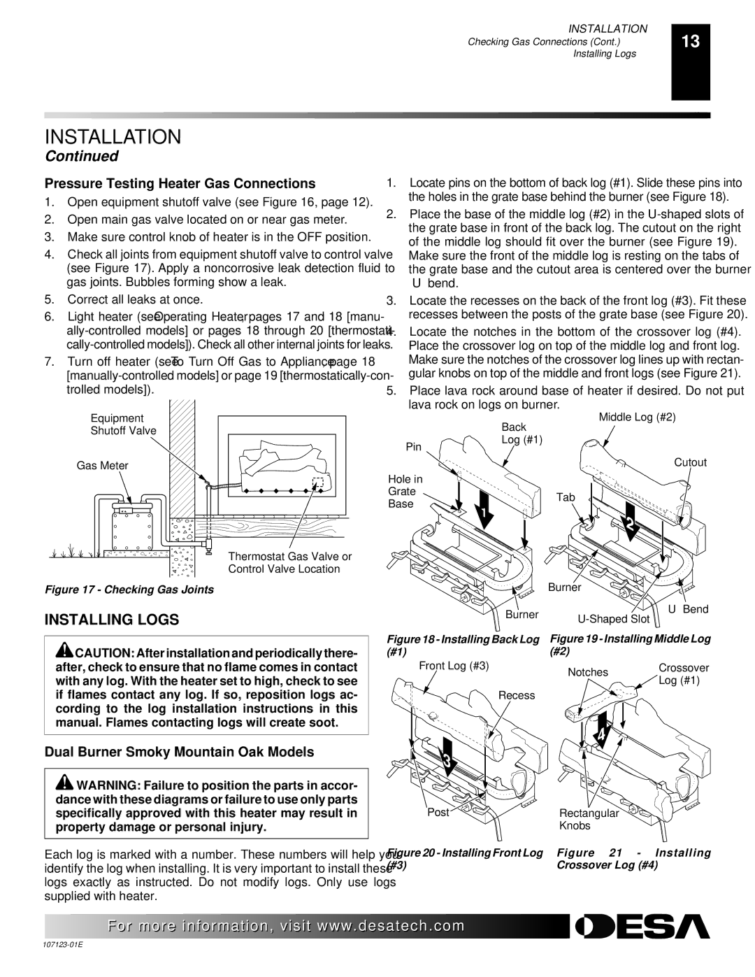
1. | Locate pins on the bottom of back log (#1). Slide these pins into |
| the holes in the grate base behind the burner (see Figure 18). |
2. | Place the base of the middle log (#2) in the |
| the grate base in front of the back log. The cutout on the right |
| of the middle log should fit over the burner (see Figure 19). |
| Make sure the front of the middle log is resting on the tabs of |
| the grate base and the cutout area is centered over the burner |
| “U” bend. |
3. | Locate the recesses on the back of the front log (#3). Fit these |
| recesses between the posts of the grate base (see Figure 20). |
4. | Locate the notches in the bottom of the crossover log (#4). |
| Place the crossover log on top of the middle log and front log. |
| Make sure the notches of the crossover log lines up with rectan- |
| gular knobs on top of the middle and front logs (see Figure 21). |
5. | Place lava rock around base of heater if desired. Do not put |
Equipment Shutoff Valve
Gas Meter
Thermostat Gas Valve or |
Control Valve Location |
lava rock on logs on burner. |
Middle Log (#2)
| Back | |
Pin | Log (#1) | |
| ||
| Cutout | |
Hole in |
| |
Grate | Tab | |
Base | ||
|
Figure 17 - Checking Gas Joints
INSTALLING LOGS
![]() CAUTION: After installation and periodically there- after, check to ensure that no flame comes in contact with any log. With the heater set to high, check to see if flames contact any log. If so, reposition logs ac- cording to the log installation instructions in this manual. Flames contacting logs will create soot.
CAUTION: After installation and periodically there- after, check to ensure that no flame comes in contact with any log. With the heater set to high, check to see if flames contact any log. If so, reposition logs ac- cording to the log installation instructions in this manual. Flames contacting logs will create soot.
Dual Burner Smoky Mountain Oak Models
![]() WARNING: Failure to position the parts in accor- dance with these diagrams or failure to use only parts specifically approved with this heater may result in property damage or personal injury.
WARNING: Failure to position the parts in accor- dance with these diagrams or failure to use only parts specifically approved with this heater may result in property damage or personal injury.
Each log is marked with a number. These numbers will help you identify the log when installing. It is very important to install these logs exactly as instructed. Do not modify logs. Only use logs supplied with heater.
| Burner |
|
Burner | “U” Bend | |
| ||
|
| |
Figure 18 - Installing Back Log | Figure 19 - Installing Middle Log | |
(#1) | (#2) |
|
Front Log (#3) | Notches | Crossover |
| Log (#1) | |
|
| |
Recess |
|
|
Post | Rectangular |
| Knobs |
Figure 20 - Installing Front Log | Figure 21 - Installing |
(#3) | Crossover Log (#4) |
For more![]()
![]()
![]()
![]() visit www.
visit www.![]()
![]()
![]() .com
.com![]()
![]()
![]()
![]()
![]()