

 Gas Instructions
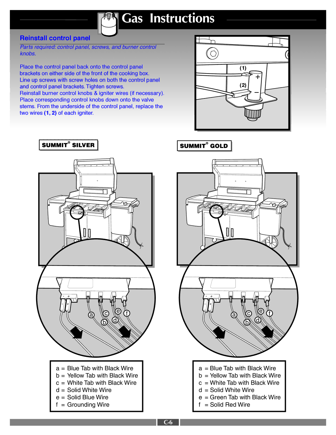
Reinstall control panel
Parts required: control panel, screws, and burner control knobs.
Place the control panel back onto the control panel | (1) | ||||||||
brackets on either side of the front of the cooking box. |
|
|
| ||||||
Line up screws with screw holes on both the control panel | (2) | ||||||||
and control panel brackets. Tighten screws. | |||||||||
Reinstall burner control knobs & igniter wires (if necessary). |
|
|
| ||||||
Place corresponding control knobs down onto the valve |
|
|
| ||||||
stems. From the underside of the control panel, replace the |
|
|
| ||||||
two wires (1, 2) of each igniter. |
|
|
| ||||||
|
|
|
|
|
|
|
|
|
|
|
|
|
|
|
|
|
|
|
|
|
|
|
|
|
|
|
|
|
|
|
|
|
|
|
|
|
|
|
|
- | + |
|
|
|
- | + |
|
|
|
| a | c | e | f |
| d | |||
|
| b |
| |
|
|
|
|
- | + |
|
|
|
- | + |
|
|
|
| a | c | e | f |
| d | |||
|
| b |
| |
|
|
|
|
a = Blue Tab with Black Wire b = Yellow Tab with Black Wire
c= White Tab with Black Wire
d= Solid White Wire
e= Solid Blue Wire
f= Grounding Wire
a= Blue Tab with Black Wire
b= Yellow Tab with Black Wire
c= White Tab with Black Wire
d= Solid White Wire
e= Green Tab with Black Wire
f= Solid Red Wire
