FIREPLACE INSTALLATION
Optional Remote Control Installation
WIRING DIAGRAM
23
FIREPLACE INSTALLATION
Continued
OPTIONAL REMOTE CONTROL
INSTALLATION (Model WRC)
Note: If using optional wireless
1.Open lower louver panel.
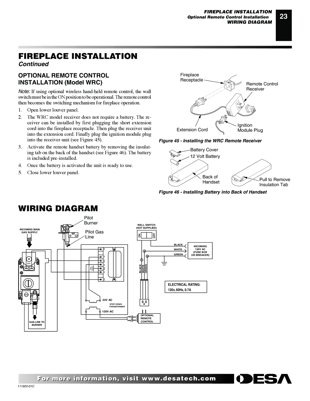
2.The WRC model receiver does not require a battery. The re- ceiver can be installed by first plugging the short extension cord into the fireplace receptacle. Then plug the receiver unit into the extension cord. Finally plug the ignition module plug into the receiver unit (see Figure 45).
3.Activate the remote handset battery by removing the insulat- ing tab on the back of the handset (see Figure 46). The battery is included
4.Once the battery is activated the unit is ready to use.
5.Close lower louver panel.
Fireplace
Receptacle
Remote Control
Receiver
Extension Cord | Ignition |
Module Plug |
Figure 45 - Installing the WRC Remote Receiver
![]() Battery Cover
Battery Cover
12 Volt Battery
Back of | Pull to Remove | |
Handset | ||
Insulation Tab | ||
|
Figure 46 - Installing Battery into Back of Handset
WIRING DIAGRAM
| Pilot | |
| Burner | |
INCOMING MAIN | Pilot Gas | |
GAS SUPPLY | ||
| Line | |
| MV | |
| TH | |
EV1 | PV/MV | |
TR | ||
| ||
| GND | |
| PV | |
| IGN |
EV2
24V AC
STEP DOWN
TRANSFORMER
120V AC
GAS LINE TO
BURNER
WALL SWITCH
(NOT SUPPLIED)
ON | OFF |
BLACK | INCOMING |
| |
WHITE | 120V AC |
GREEN | (FUSE BOX |
OR BREAKER) |
BLACK | WHITE | GREEN |
ELECTRICAL RATING:
120v, 60Hz, 0.7A
OPTIONAL
REMOTE
CONTROL
![]() For more
For more![]()
![]()
![]() visit www.
visit www.![]()
![]()
![]() .com
.com![]()
![]()
![]()
![]()
![]()
![]()