INSTALLATION

Gas Line Hook-Up (Cont.)

11

INSTALLATION

Continued

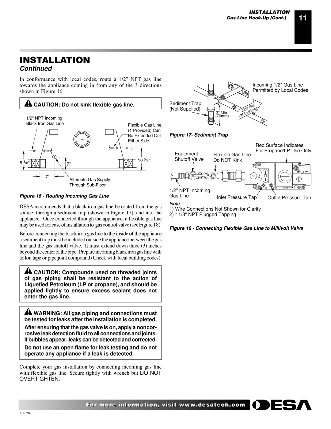
In conformance with local codes, route a 1/2" NPT gas line towards the appliance coming in from any of the 3 directions shown in Figure 16.

CAUTION: Do not kink flexible gas line.


Incoming 1/2" Gas Line


Permitted by Local Codes

Sediment Trap


Wall

(Not Supplied)


Side

3" Min.


Appliance

(76mm)

Of

1/2" NPT Incoming

Black Iron Gas Line


8

3/8"


7"


7"

Alternate Gas Supply Through Sub-Floor

Flexible Gas Line

(1 Provided) Can

Be Extended Out

Either Side

105/8"

Figure 17- Sediment Trap


Red Surface Indicates

Equipment

For Propane/LP Use Only

Flexible Gas Line

Shutoff Valve

Do NOT Kink

Figure 16 - Routing Incoming Gas Line

DESA recommends that a black iron gas line be routed from the gas source, through a sediment trap (shown in Figure 17), and into the appliance, Once connected through the appliance, a flexible gas line may be used for ease of installation to gas control valve (see Figure 18).

1/2" NPT Incoming


Gas Line

Inlet Pressure Tap

Outlet Pressure Tap


Note:

1)Wire Connections Not Shown for Clarity

2)* 1/8" NPT Plugged Tapping

Figure 18 - Connecting Flexible Gas Line to Millivolt Valve

Before connecting the black iron gas line to the inside of the appliance a sediment trap must be included outside the appliance between the gas line and the gas shutoff valve. It must extend down three (3) inches beyond the center of the pipe. Prepare incoming black iron gas line with teflon tape or pipe joint compound (Check with local building codes).

CAUTION: Compounds used on threaded joints of gas piping shall be resistant to the action of Liquefied Petroleum (LP or propane), and should be applied lightly to ensure excess sealant does not enter the gas line.

WARNING: All gas piping and connections must be tested for leaks after the installation is completed.

After ensuring that the gas valve is on, apply a noncor- rosive leak detection fluid to all connections and joints. If bubbles appear, leaks can be detected and corrected.

Do not use an open flame for leak testing and do not operate any appliance if a leak is detected.

Complete your gas installation by connecting incoming gas line with flexible gas line. Secure tightly with wrench but DO NOT

OVERTIGHTEN.

For more information, visit www.desatech.com

108794

Page 11
Image 11
Desa P324E, VP324E, P325E, VP325E, P325E(B), VP325E(B) installation manual Overtighten

VP324E, P324E, VP324E, P325E, VP325E, P325E(B), VP325E(B) specifications

Desa P324E, VP324E, P325E, VP325E, P325E(B), VP325E(B), and VP324E are a series of advanced pumps designed to meet the diverse needs of industrial applications. These pumps are renowned for their efficiency, durability, and versatility, making them an ideal choice for various sectors such as manufacturing, chemical processing, and water management.

The main features of these pump models lie in their robust construction and innovative design. They are built using high-quality materials that ensure longevity and resistance to corrosive environments. The pumps also feature advanced sealing technologies that minimize leakage risks, thus enhancing operational safety and reliability.

One of the standout technologies in these models is their semi-open impeller design, which provides superior hydraulic performance. This design allows for handling solids and slurries effectively, making them suitable for applications where traditional pumps might struggle. The pumps also boast a user-friendly interface that simplifies operation and maintenance, reducing downtime and operational costs.

The Desa P324E and VP324E models are known for their compact size and high flow rate capabilities, making them suitable for space-constrained installations. In contrast, the P325E series, including the VP325E and its variants, offers enhanced performance specifications with improved energy efficiency. This is achieved through an innovative motor design that ensures lower energy consumption without compromising output.

The pumps are equipped with intelligent monitoring systems, allowing for real-time assessment of performance metrics. This feature enables predictive maintenance, significantly extending the lifespan of the equipment and minimizing unexpected failures. Additionally, the integration of advanced control systems allows users to customize operational parameters according to specific application needs.

Each model within the series can be tailored with various options, including different mounting configurations, motor types, and material finishes. This adaptability ensures that the pumps can be effectively integrated into existing systems and meet specific industry standards.

In summary, the Desa P324E, VP324E, P325E, VP325E, P325E(B), VP325E(B), and VP324E series represent a culmination of engineering excellence, designed to address the demands of modern industrial applications. With their combination of advanced technology, robust design, and flexibility, these pumps offer reliable performance that can be counted on across a range of challenging environments.