ASSEMBLY INSTRUCTIONS
Continued
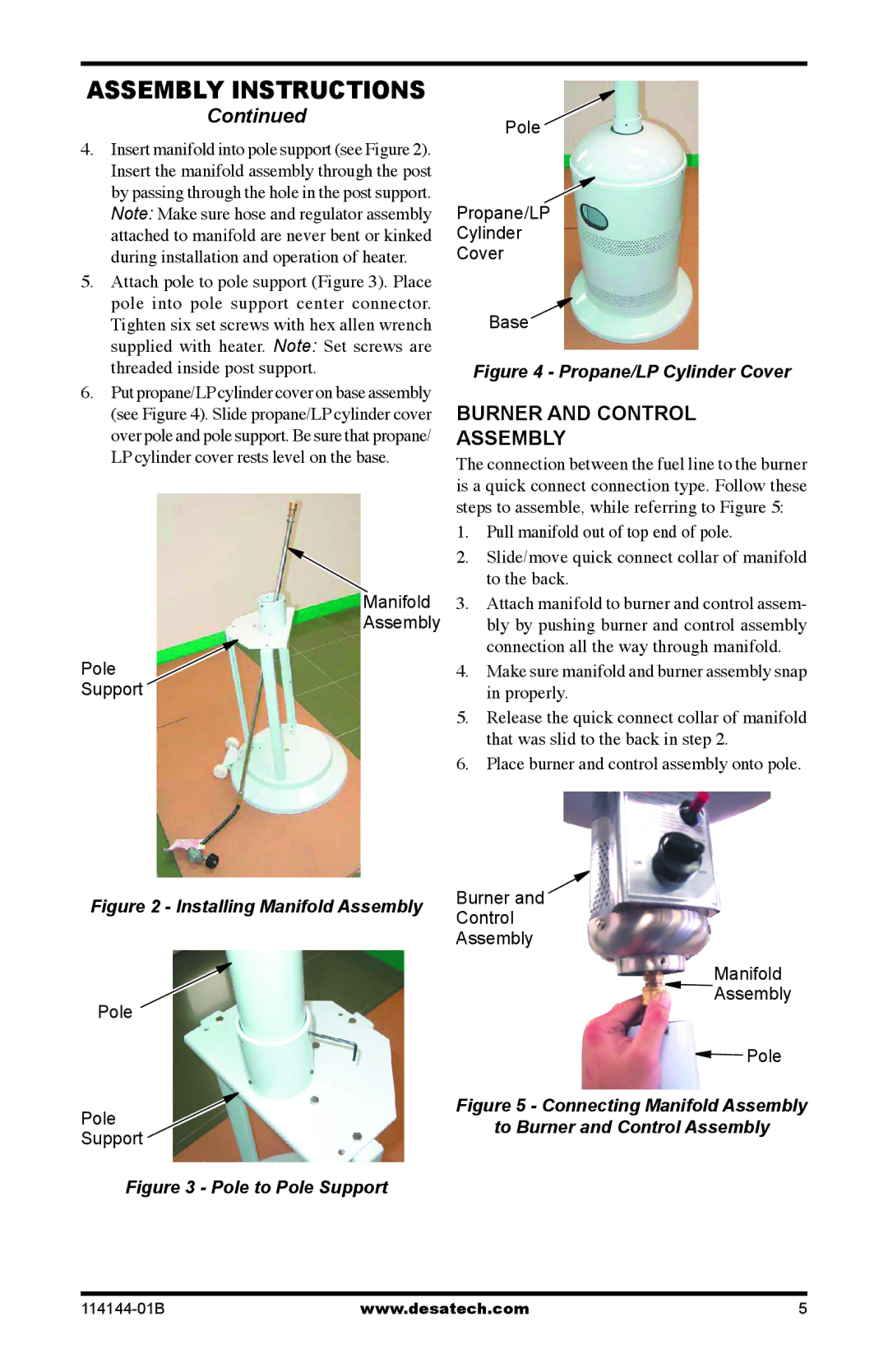
4.Insert manifold into pole support (see Figure 2). Insert the manifold assembly through the post by passing through the hole in the post support. Note: Make sure hose and regulator assembly attached to manifold are never bent or kinked during installation and operation of heater.
5.Attach pole to pole support (Figure 3). Place pole into pole support center connector. Tighten six set screws with hex allen wrench supplied with heater. Note: Set screws are threaded inside post support.
6.Put propane/LPcylinder cover on base assembly (see Figure 4). Slide propane/LP cylinder cover over pole and pole support. Be sure that propane/ LP cylinder cover rests level on the base.
Manifold
Assembly
Pole
Support
Figure 2 - Installing Manifold Assembly
Pole
Pole
Support
Figure 3 - Pole to Pole Support
Pole ![]()
Propane/LP
Cylinder
Cover
Base
Figure 4 - Propane/LP Cylinder Cover
BURNER AND CONTROL
ASSEMBLY
The connection between the fuel line to the burner is a quick connect connection type. Follow these steps to assemble, while referring to Figure 5:
1.Pull manifold out of top end of pole.
2.Slide/move quick connect collar of manifold to the back.
3.Attach manifold to burner and control assem- bly by pushing burner and control assembly connection all the way through manifold.
4.Make sure manifold and burner assembly snap in properly.
5.Release the quick connect collar of manifold that was slid to the back in step 2.
6.Place burner and control assembly onto pole.
Burner and
Control
Assembly
Manifold
![]() Assembly
Assembly
![]() Pole
Pole
Figure 5 - Connecting Manifold Assembly to Burner and Control Assembly
www.desatech.com | 5 |
