INSTALLATION
Continued
2.Remove 4 screws from upper louver (see Figure 11, page 12). Save these screws.
3.Pull upper louver straight out from the cabinet. Be careful not to scratch the paint. Set louver aside.
4.Open lower louver door by swinging door down (see Figure 11, page 12).
Installing Blower Accessory
![]() CAUTION: Label all wires prior to disconnection when ser- vicingcontrols.Wiringerrorscan cause improper and dangerous operation.
CAUTION: Label all wires prior to disconnection when ser- vicingcontrols.Wiringerrorscan cause improper and dangerous operation.
![]() CAUTION: Verify proper op- eration after servicing.
CAUTION: Verify proper op- eration after servicing.
Note: If you are using a mantel with your fireplace, use the following instructions. If your fireplace is
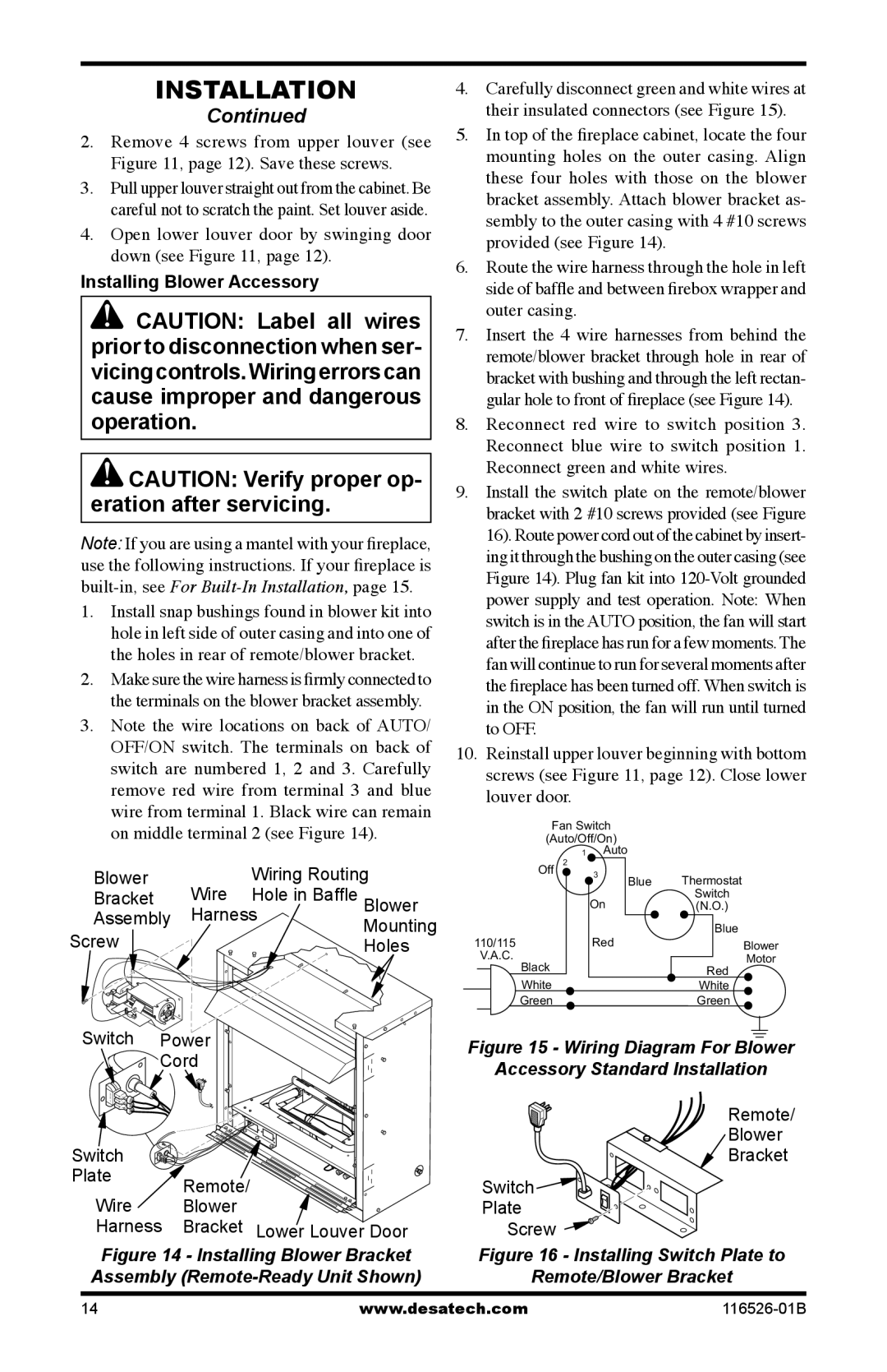
1.Install snap bushings found in blower kit into hole in left side of outer casing and into one of the holes in rear of remote/blower bracket.
2.Make sure the wire harness is firmly connected to the terminals on the blower bracket assembly.
3.Note the wire locations on back of AUTO/ OFF/ON switch. The terminals on back of switch are numbered 1, 2 and 3. Carefully remove red wire from terminal 3 and blue wire from terminal 1. Black wire can remain on middle terminal 2 (see Figure 14).
Blower | Wire | Wiring Routing | ||
Bracket | Hole in Baffle | Blower | ||
Assembly | Harness | |||
Mounting | ||||
Screw |
|
| ||
|
| Holes | ||
Switch Power |
|
| ||
Cord |
|
| ||
3 |
|
|
| |
2 |
|
|
| |
1 |
|
|
| |
Switch |
|
|
| |
Plate | Remote/ |
|
| |
Wire |
|
| ||
Blower |
|
| ||
Harness | Bracket | Lower Louver Door | ||
Figure 14 - Installing Blower Bracket Assembly (Remote-Ready Unit Shown)
4.Carefully disconnect green and white wires at their insulated connectors (see Figure 15).
5.In top of the fireplace cabinet, locate the four mounting holes on the outer casing. Align these four holes with those on the blower bracket assembly. Attach blower bracket as- sembly to the outer casing with 4 #10 screws provided (see Figure 14).
6.Route the wire harness through the hole in left side of baffle and between firebox wrapper and outer casing.
7.Insert the 4 wire harnesses from behind the remote/blower bracket through hole in rear of bracket with bushing and through the left rectan- gular hole to front of fireplace (see Figure 14).
8.Reconnect red wire to switch position 3. Reconnect blue wire to switch position 1. Reconnect green and white wires.
9.Install the switch plate on the remote/blower bracket with 2 #10 screws provided (see Figure 16). Route power cord out of the cabinet by insert- ing it through the bushing on the outer casing (see Figure 14). Plug fan kit into
10.Reinstall upper louver beginning with bottom screws (see Figure 11, page 12). Close lower louver door.
Fan Switch
(Auto/Off/On)
1Auto
|
| Off | 2 |
|
|
|
|
|
| 3 | Blue | Thermostat | |
|
|
|
|
| ||
|
|
| On |
| Switch | |
|
|
|
| (N.O.) | ||
|
|
|
|
|
| Blue |
110/115 | Red |
| Blower | |||
| V.A.C. |
|
|
| Motor | |
|
| Black |
|
|
| Red |
|
|
|
|
| ||
|
| White |
|
|
| White |
|
| Green |
|
|
| Green |
Figure 15 - Wiring Diagram For Blower
Accessory Standard Installation
Remote/
Blower
Bracket
Switch

Plate
Screw 

Figure 16 - Installing Switch Plate to
Remote/Blower Bracket
14 | www.desatech.com |