CLEANING AND
MAINTENANCE
Continued
We also recommend that you keep the burner tube and pilot assembly clean and free of dust and dirt. To clean these parts we recommend using compressed air no greater than 30 PSI. Your local computer store, hardware store or home center may carry compressed air in a can. You can use a vacuum cleaner in the blow position. If using com- pressed air in a can, please follow the directions on the can. If you don’t follow directions on the can, you could damage the pilot assembly.
1.Shut off the unit, including the pilot. Allow the unit to cool for at least thirty minutes.
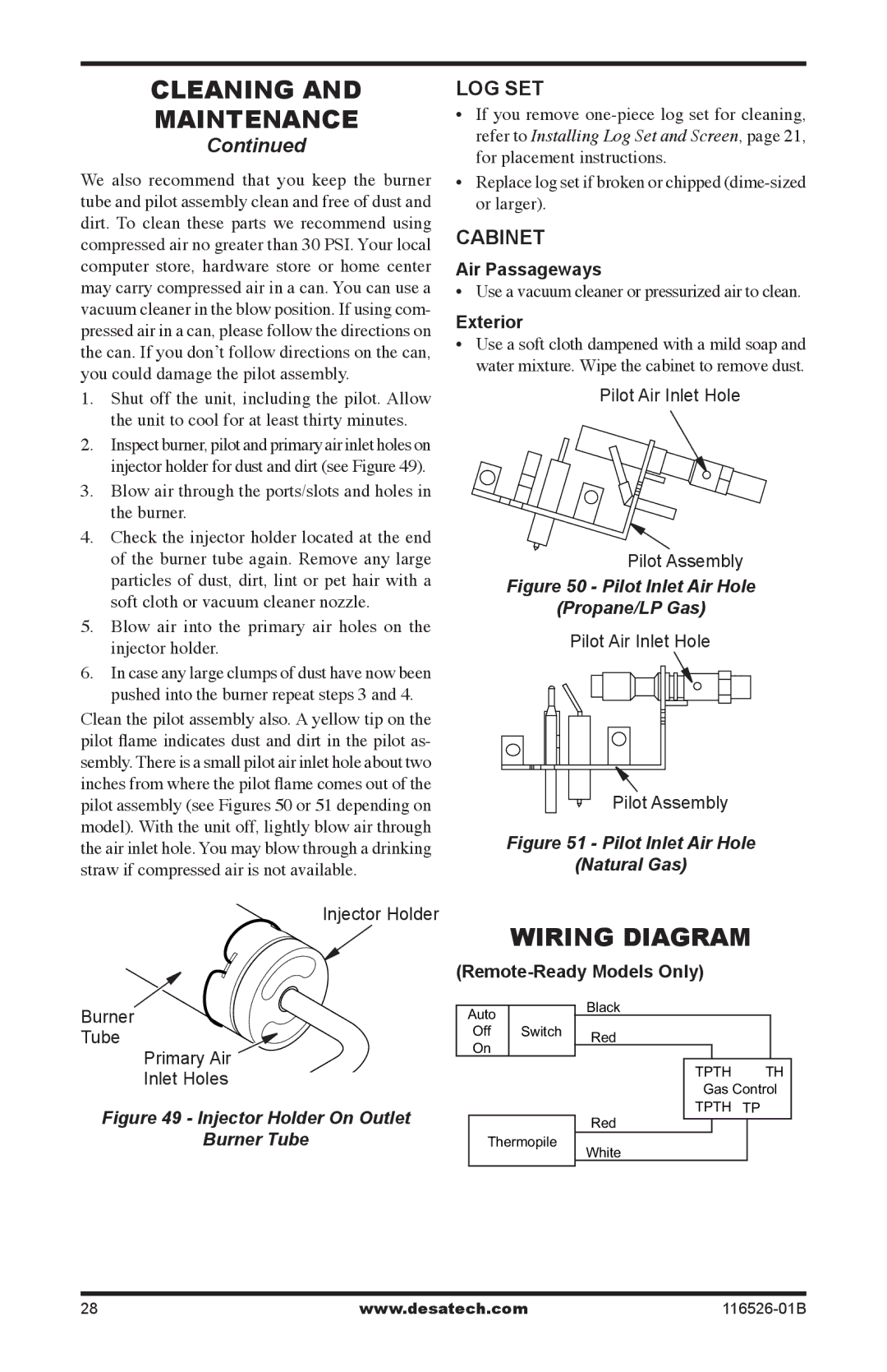
2.Inspect burner, pilot and primary air inlet holes on injector holder for dust and dirt (see Figure 49).
3.Blow air through the ports/slots and holes in the burner.
4.Check the injector holder located at the end of the burner tube again. Remove any large particles of dust, dirt, lint or pet hair with a soft cloth or vacuum cleaner nozzle.
5.Blow air into the primary air holes on the injector holder.
6.In case any large clumps of dust have now been pushed into the burner repeat steps 3 and 4.
Clean the pilot assembly also. A yellow tip on the pilot flame indicates dust and dirt in the pilot as- sembly. There is a small pilot air inlet hole about two inches from where the pilot flame comes out of the pilot assembly (see Figures 50 or 51 depending on model). With the unit off, lightly blow air through the air inlet hole. You may blow through a drinking straw if compressed air is not available.
Injector Holder
Burner
Tube
Primary Air
LOG Set
•If you remove
•Replace log set if broken or chipped
CABINET
Air Passageways
• Use a vacuum cleaner or pressurized air to clean.
Exterior
• Use a soft cloth dampened with a mild soap and water mixture. Wipe the cabinet to remove dust.
Pilot Air Inlet Hole
Pilot Assembly
Figure 50 - Pilot Inlet Air Hole
(Propane/LP Gas)
Pilot Air Inlet Hole
Pilot Assembly
Figure 51 - Pilot Inlet Air Hole
(Natural Gas)
Wiring Diagram
(Remote-Ready Models Only)
|
| Black |
| ||
Auto |
|
| |||
Off | Switch | Red |
| ||
On |
|
| |||
|
|
|
|
| |
|
|
|
|
|
|
Inlet Holes
Figure 49 - Injector Holder On Outlet
Burner Tube
Thermopile
TPTH TH
Gas Control
TPTH TP
Red
White
28 | www.desatech.com |