INSTALLATION
Continued
Installation Items Needed
•control cover kit (provided with heater)
•approved flexible gas hose (not provided) (if allowed by local codes)
•sealant (resistant to propane/LP gas, not provided)
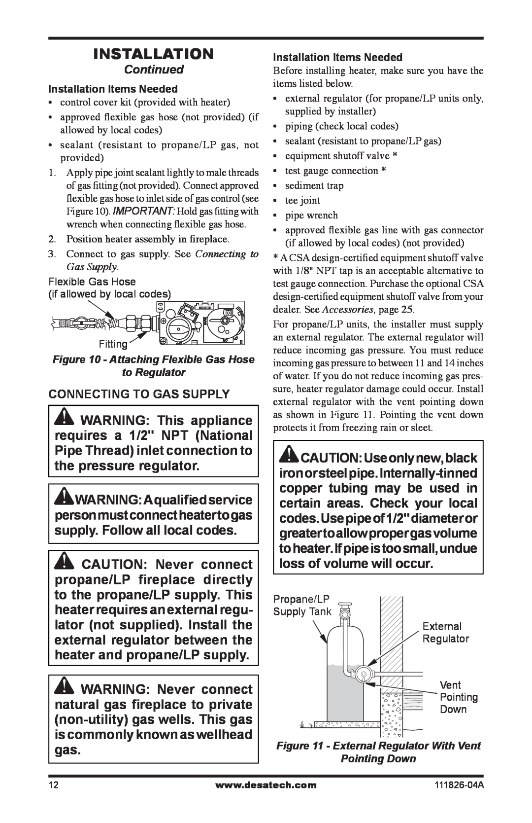
1.Apply pipe joint sealant lightly to male threads of gas fitting (not provided). Connect approved flexible gas hose to inlet side of gas control (see Figure 10). IMPORTANT: Hold gas fitting with wrench when connecting flexible gas hose.
2.Position heater assembly in fireplace.
3.Connect to gas supply. See Connecting to Gas Supply.
Flexible Gas Hose
(if allowed by local codes)
Fitting ![]()
Figure 10 - Attaching Flexible Gas Hose
to Regulator
CONNECTING TO GAS SUPPLY
![]() WARNING: This appliance requires a 1/2" NPT (National Pipe Thread) inlet connection to the pressure regulator.
WARNING: This appliance requires a 1/2" NPT (National Pipe Thread) inlet connection to the pressure regulator.
![]() WARNING:Aqualifiedservice personmustconnectheatertogas supply. Follow all local codes.
WARNING:Aqualifiedservice personmustconnectheatertogas supply. Follow all local codes.
![]() CAUTION: Never connect propane/LP fireplace directly to the propane/LP supply. This heater requires an external regu- lator (not supplied). Install the external regulator between the heater and propane/LP supply.
CAUTION: Never connect propane/LP fireplace directly to the propane/LP supply. This heater requires an external regu- lator (not supplied). Install the external regulator between the heater and propane/LP supply.
![]() WARNING: Never connect natural gas fireplace to private
WARNING: Never connect natural gas fireplace to private
Installation Items Needed Before installing heater, make sure you have the items listed below.
•external regulator (for propane/LP units only, supplied by installer)
•piping (check local codes)
•sealant (resistant to propane/LP gas)
•equipment shutoff valve *
•test gauge connection *
•sediment trap
•tee joint
•pipe wrench
•approved flexible gas line with gas connector (if allowed by local codes) (not provided)
*A CSA
For propane/LP units, the installer must supply an external regulator. The external regulator will reduce incoming gas pressure. You must reduce incoming gas pressure to between 11 and 14 inches of water. If you do not reduce incoming gas pres- sure, heater regulator damage could occur. Install external regulator with the vent pointing down as shown in Figure 11. Pointing the vent down protects it from freezing rain or sleet.
![]() CAUTION:Useonlynew,black
CAUTION:Useonlynew,black
Propane/LP
Supply Tank
External
![]() Regulator
Regulator
Vent
Pointing
Down
Figure 11 - External Regulator With Vent Pointing Down
12 | www.desatech.com |
