Installation
Continued
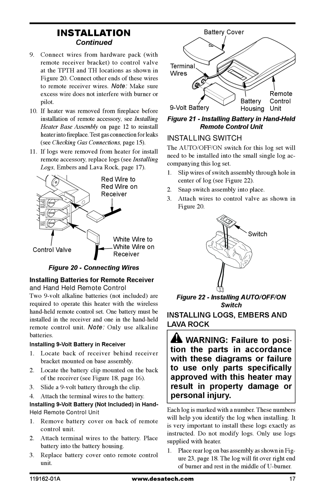
9.Connect wires from hardware pack (with remote receiver bracket) to control valve at the TPTH and TH locations as shown in Figure 20. Connect other ends of these wires to remote receiver wires. Note: Make sure excess wire does not interfere with burner or pilot.
10.If heater was removed from fireplace before installation of remote accessory, see Installing Heater Base Assembly on page 12 to reinstall heater into fireplace. Test gas connection for leaks (see Checking Gas Connections, page 15).
11.If logs were removed from heater for install remote accessory, replace logs (see Installing Logs, Embers and Lava Rock, page 17).
Red Wire to
Red Wire on
Receiver
White Wire to
Control Valve ![]()
![]() White Wire on Receiver
White Wire on Receiver
Figure 20 - Connecting Wires
Installing Batteries for Remote Receiver
and Hand Held Remote Control
Two
Installing
1.Locate back of receiver behind receiver bracket mounted on base assembly.
2.Locate the battery clip mounted on the back of the receiver (see Figure 18, page 16).
3.Slide a
4.Attach the terminal wires to the battery.
Installing
Held Remote Control Unit
1.Remove battery cover on back of remote control unit.
2.Attach terminal wires to the battery. Place battery into the battery housing.
3.Replace battery cover onto remote control unit.
Battery Cover
Terminal
Wires
|
| Remote |
Battery | Control | |
Housing | Unit |
Figure 21 - Installing Battery in Hand-Held
Remote Control Unit
Installing Switch
The AUTO/OFF/ON switch for this log set will need to be installed into the small single log ac- companying this log set.
1.Slip wires of switch assembly through hole in center of log (see Figure 22).
2.Snap switch assembly into place.
3.Attach wires to control valve as shown in Figure 20.
![]() Switch
Switch
Figure 22 - Installing AUTO/OFF/ON
Switch
INSTALLING LOGS, Embers and Lava Rock
![]() WARNING: Failure to posi- tion the parts in accordance with these diagrams or failure to use only parts specifically approved with this heater may result in property damage or personal injury.
WARNING: Failure to posi- tion the parts in accordance with these diagrams or failure to use only parts specifically approved with this heater may result in property damage or personal injury.
Each log is marked with a number. These numbers will help you identify the log when installing. It is very important to install these logs exactly as instructed. Do not modify logs. Only use logs supplied with heater.
1.Place rear log on bas assembly as shown in Fig- ure 23, page 18. The log will fit over right end of burner and rest in the middle of
www.desatech.com | 17 |