Venting Installation
instructions
Continued
INSTALLATION PLANNING
There are two basic types of
•Horizontal Termination
•Vertical Termination
Horizontal Termination Installation IMPORTANT: Horizontal square terminations require only inner portion of wall firestop. Hori- zontal installations using round termination require exterior portion of wall firestop (see Figure 14, page 12).
1. Set the fireplace in its desired location and deter- |
mine the route your horizontal venting will take. |
Do not secure the fireplace until all venting has |
been installed. Some installations require sliding |
the fireplace in and out of position to make final |
venting connections. Figures 14 through 18 on |
pages 12 through 14 show different configura- |
tions for venting with horizontal termination that |
will help you decide which application best suits |
your installation. Check to see if wall studs or |
roof rafters are in the path of your desired vent- |
ing route. If they are, you may want to adjust the |
location of the fireplace. |
2. Direct vent pipe sections and components are |
designed with special |
5.Carefully determine the location where the vent pipe assembly will penetrate the outside wall. The center of the hole should line up with the
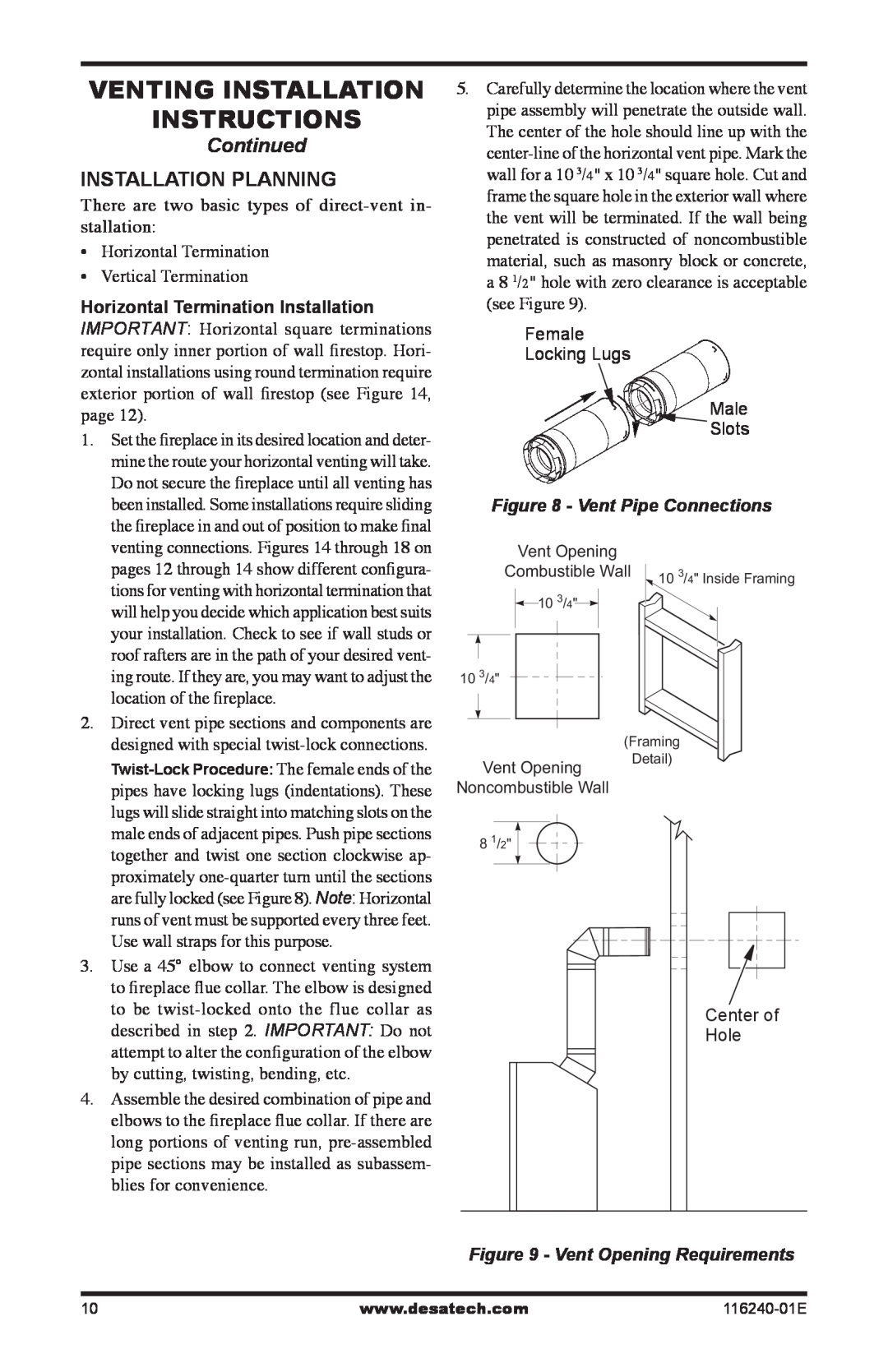
Female
Locking Lugs
Male
![]() Slots
Slots
Figure 8 - Vent Pipe Connections
Vent Opening
Combustible Wall | 10 3/4" Inside Framing |
10 3/4" |
|
103/4"
(Framing
Vent Opening
Detail)
pipes have locking lugs (indentations). These |
lugs will slide straight into matching slots on the |
male ends of adjacent pipes. Push pipe sections |
together and twist one section clockwise ap- |
proximately |
are fully locked (see Figure 8). Note: Horizontal |
runs of vent must be supported every three feet. |
Use wall straps for this purpose. |
3. Use a 45° elbow to connect venting system |
to fireplace flue collar. The elbow is designed |
to be |
described in step 2. IMPORTANT: Do not |
attempt to alter the configuration of the elbow |
by cutting, twisting, bending, etc. |
4. Assemble the desired combination of pipe and |
elbows to the fireplace flue collar. If there are |
long portions of venting run, |
pipe sections may be installed as subassem- |
blies for convenience. |
Noncombustible Wall
8 1/2" |
Center of |
Hole |
Figure 9 - Vent Opening Requirements
10 | www.desatech.com |