® VMH26PR

COMPACT CLASSIC HEARTH FIREPLACE

INSTALLATION

Continued

Mantel Clearances for Built-In Installation

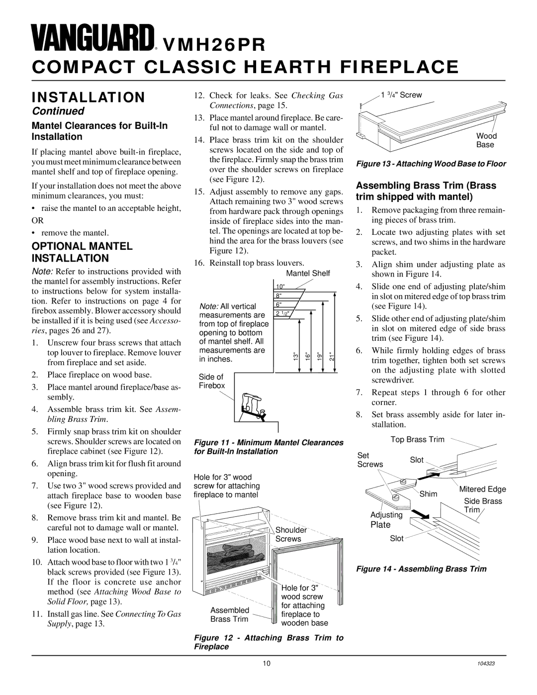
If placing mantel above built-in fireplace, you must meet minimum clearance between mantel shelf and top of fireplace opening.

If your installation does not meet the above minimum clearances, you must:

raise the mantel to an acceptable height,

OR

remove the mantel.

OPTIONAL MANTEL

INSTALLATION

Note: Refer to instructions provided with the mantel for assembly instructions. Refer to instructions below for system installa- tion. Refer to instructions on page 4 for firebox assembly. Blower accessory should be installed if it is being used (see Accesso- ries, pages 26 and 27).

1.

Unscrew four brass screws that attach


top louver to fireplace. Remove louver


from fireplace and set aside.

2.

Place fireplace on wood base.

3.

Place mantel around fireplace/base as-


sembly.

4.

Assemble brass trim kit. See Assem-


bling Brass Trim.

5.

Firmly snap brass trim kit on shoulder


screws. Shoulder screws are located on


fireplace cabinet (see Figure 12).

12.Check for leaks. See Checking Gas Connections, page 15.

13.Place mantel around fireplace. Be care- ful not to damage wall or mantel.

14.Place brass trim kit on the shoulder screws located on the side and top of the fireplace. Firmly snap the brass trim over the shoulder screws on fireplace (see Figure 12).

15.Adjust assembly to remove any gaps. Attach remaining two 3" wood screws from hardware pack through openings inside of fireplace sides into the man- tel. The openings are located at top be- hind the area for the brass louvers (see Figure 12).

16.Reinstall top brass louvers.


Mantel Shelf


10"


8"


Note: All vertical

6"


measurements are

2 1/2"


from top of fireplace


opening to bottom


of mantel shelf. All


measurements are

13"

16"

19"

21"

in inches.


Side of


Firebox


Figure 11 - Minimum Mantel Clearances for Built-In Installation

1 3/4" Screw

Wood

Base

Figure 13 - Attaching Wood Base to Floor

Assembling Brass Trim (Brass trim shipped with mantel)

1.Remove packaging from three remain- ing pieces of brass trim.

2.Locate two adjusting plates with set screws, and two shims in the hardware packet.

3.Align shim under adjusting plate as shown in Figure 14.

4.Slide one end of adjusting plate/shim in slot on mitered edge of top brass trim (see Figure 14).

5.Slide other end of adjusting plate/shim in slot on mitered edge of side brass trim (see Figure 14).

6.While firmly holding edges of brass trim together, tighten both set screws on the adjusting plate with slotted screwdriver.

7.Repeat steps 1 through 6 for other corner.

8.Set brass assembly aside for later in- stallation.

Top Brass Trim

SetSlot

6.

Align brass trim kit for flush fit around


opening.

7.

Use two 3" wood screws provided and


attach fireplace base to wooden base

Hole for 3" wood screw for attaching fireplace to mantel

Screws

Shim

Mitered Edge

(see Figure 12).

8. Remove brass trim kit and mantel. Be

careful not to damage wall or mantel.

Shoulder

Adjusting

Plate

Side Brass Trim

9.

Place wood base next to wall at instal-


lation location.

10.

Attach wood base to floor with two 1 3/4"


black screws provided (see Figure 13).


If the floor is concrete use anchor


method (see Attaching Wood Base to


Solid Floor, page 13).

11.

Install gas line. See Connecting To Gas


Supply, page 13.

Screws


Hole for 3"


wood screw

Assembled

for attaching

fireplace to

Brass Trim

wooden base


Figure 12 - Attaching Brass Trim to Fireplace

Slot

Figure 14 - Assembling Brass Trim

10

104323

Page 10
Image 10
Desa VMH26PR installation manual Optional Mantel Installation, Mantel Clearances for Built-In Installation

VMH26PR specifications

Desa VMH26PR is a cutting-edge horizontal multistage pump designed for a variety of applications, primarily in industrial and municipal sectors. Its robust construction delivers excellent performance and reliability, making it a preferred choice for demanding environments.

One of the primary features of the VMH26PR is its versatile design. Engineered for efficiency, it is capable of handling a wide range of fluids, including clean water, chemicals, and other industrial liquids. This pump is particularly known for its ability to operate under high-pressure conditions while maintaining a low energy consumption rate, which is a significant advantage in terms of operational costs.

The VMH26PR incorporates advanced hydraulic technologies, which enhance both performance and efficiency. The multistage configuration allows for higher pressure generation, making it ideal for applications that require elevated discharge pressures. Each stage is meticulously designed to optimize flow, reducing turbulence and maximizing throughput. This results in improved overall system efficiency and longevity of the pump.

In terms of materials, the VMH26PR offers various casing options tailored to the specific needs of the application, including stainless steel and cast iron. These materials provide excellent resistance to corrosion and wear, ensuring durability even in harsh environments. Additionally, the pump features mechanical seals designed to minimize leakage and enhance reliability.

Another significant technological aspect of the VMH26PR is its modular design. This allows for easy maintenance and component replacement, reducing downtime and service costs. Users can easily access vital parts without disassembling the entire unit, which is a considerable advantage for operation in critical settings.

Moreover, the Desa VMH26PR is equipped with a range of monitoring and control options, enabling seamless integration into automated processes. This feature enhances operational efficiency, allowing operators to monitor performance parameters in real-time and make data-driven decisions to optimize performance.

Overall, the Desa VMH26PR stands out with its combination of efficiency, durability, and ease of maintenance, making it an ideal solution for various fluid handling tasks across different industries. Its ability to adapt to specific requirements and conditions ensures it will meet the diverse needs of modern applications effectively.