Installation
Continued
1.Frame in rough opening. Use dimensions shown in Figure 13 for the rough opening. If installing in a corner, use dimensions shown in Figure 14 for the rough opening. The height is 33" which is the same as the wall opening above.
2.If using blower, install and properly ground GA3555,
3.Install gas piping into fireplace location. This installation includes an approved flexible gas line (if allowed by local codes) after the equip- ment shutoff valve. The flexible gas line must be the last item installed on the gas piping. See
Installing Gas Piping to Fireplace Location, page 13.
4.Carefully set fireplace in front of rough opening with back of fireplace inside wall opening.
5.Carefully insert fireplace into rough opening.
6.Attach flexible gas line to gas supply. See Con- necting Fireplace to Gas Supply, page 14.
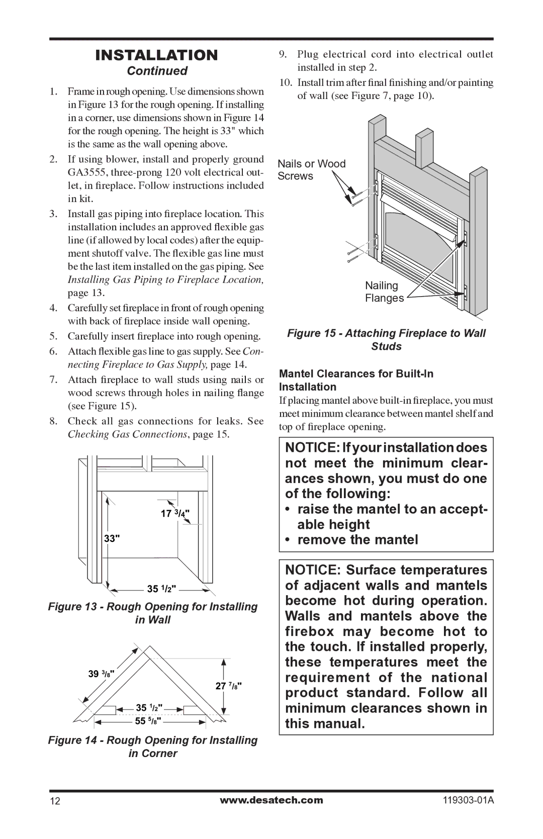
7.Attach fireplace to wall studs using nails or wood screws through holes in nailing flange (see Figure 15).
8.Check all gas connections for leaks. See
Checking Gas Connections, page 15.
17 3/4"
33"
![]()
![]() 35 1/2"
35 1/2" ![]()
Figure 13 - Rough Opening for Installing
in Wall
393/8"
27 7/8"
![]() 35 1/2"
35 1/2" ![]() 55 5/8"
55 5/8"
Figure 14 - Rough Opening for Installing
in Corner
9.Plug electrical cord into electrical outlet installed in step 2.
10.Install trim after final finishing and/or painting of wall (see Figure 7, page 10).
Nails or Wood
Screws
Nailing
Flanges ![]()
![]()
Figure 15 - Attaching Fireplace to Wall
Studs
Mantel Clearances for Built-In
Installation
If placing mantel above
Notice: If your installation does not meet the minimum clear- ances shown, you must do one of the following:
•raise the mantel to an accept- able height
•remove the mantel
NOTICE: Surface temperatures of adjacent walls and mantels become hot during operation. Walls and mantels above the firebox may become hot to the touch. If installed properly, these temperatures meet the requirement of the national product standard. Follow all minimum clearances shown in this manual.
12 | www.desatech.com |