Desa VV36ENC1 SERIES Venting Installation instructions, Continued, Vent Pipe Connections

Models: VV36EPC1 SERIES (V)V36EP-B VV36ENC1 SERIES (V)V36EN-B

1 34
Download 34 pages 58.71 Kb
Page 8
Image 8
Venting Installation

Venting Installation

instructions

Continued

2.Direct vent pipe sections and components are designed with special twist-lock connections.

Twist-Lock Procedure: The female ends of the pipes have locking lugs (indentations). These lugs will slide straight into matching slots on the male ends of adjacent pipes. Push pipe sections together and twist one section clockwise approxi- mately one-quarter turn until the sections are fully locked (see Figure 8). Note: Horizontal runs of vent must be supported every three feet. Use wall straps for this purpose.

3.Use a 45° elbow to connect venting system to fireplace flue collar. The elbow is designed to be twist-locked onto the flue collar as described in step 2. IMPORTANT: Do not attempt to alter the configuration of the elbow by cutting, twisting, bending, etc.

4.Assemble the desired combination of pipe and elbows to the fireplace. If there are long portions of venting run, pre-as- sembled pipe sections may be installed as subassemblies for convenience.

5.Carefully determine the location where the vent pipe assembly will penetrate the outside wall. The center of the hole should line up with the center-line of the horizontal vent pipe. Mark the wall for a 10 3/4" x 10 3/4" square hole. Cut and frame the square hole in the exterior wall where the vent will be terminated. If the wall being penetrated is constructed of noncombustible material, such as masonry block or concrete, a 8 1/2" hole with zero clearance is acceptable (see Figure 9).

Figure 8 - Vent Pipe Connections WARNING: Do not recess vent termination into any wall. This will cause a fire hazard.

6.Noncombustible Exterior Wall: Position the horizontal vent cap in the center of the 8 1/2" round hole and attach to the exterior wall with four wood screws provided. Before attach- ing the vent cap to exterior wall, run a bead of non-hardening mastic (pliable sealant) around the outside edges to make a seal between it and the outside wall. Note: The four wood screws provided should be replaced with appropriate fasteners for stucco, brick, concrete, or other types of sidings.

Combustible Exterior Wall: For vinyl siding, stucco, or wood exteriors, a siding standoff must be installed between the vent cap and exterior wall. The siding standoff prevents excessive heat from damaging the siding materials. Siding material must be cut to accommodate standoff. Bolt the vent cap to the standoff. Apply
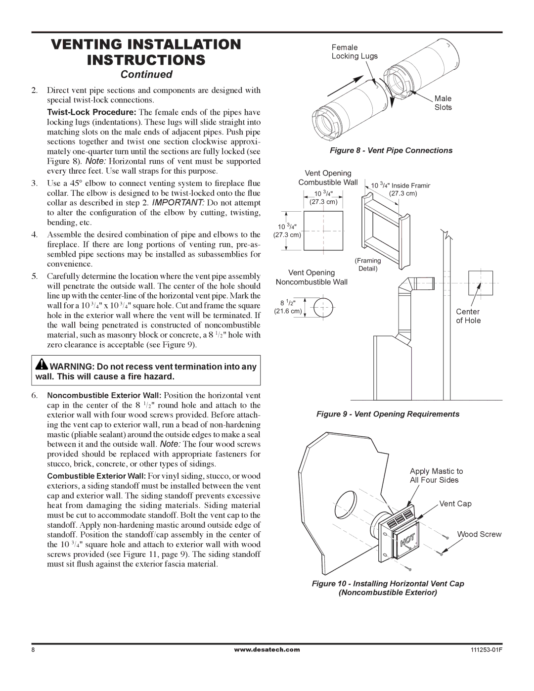
 non-hardening mastic around outside edge of standoff. Position the standoff/cap assembly in the center of the 10 3/4" square hole and attach to exterior wall with wood screws provided (see Figure 11, page 9). The siding standoff must sit flush against the exterior fascia material.

Female

Locking Lugs

Figure 9 - Vent Opening Requirements Male

Slots

Figure 8 - Vent Pipe Connections

Vent Opening

Combustible Wall


10 3/4" Inside Framin


10 3/4"


(27.3 cm)


(27.3 cm)


10 3/4"


(27.3 cm)


(Framing

Vent Opening

Detail)


Noncombustible Wall


8 1/2"


(21.6 cm)

Center


of Hole

Figure 9 - Vent Opening Requirements

Apply Mastic to

All Four Sides

Vent Cap

Wood Screw

Figure 10 - Installing Horizontal Vent Cap

(Noncombustible Exterior)

www.desatech.com

111253-01F

Page 8
Image 8
Desa VV36ENC1 SERIES Venting Installation instructions, Continued, Vent Pipe Connections, Vent Opening Requirements