SPECIFICATIONS
| ||||
| ||||
| ||||
Btu (Variable) | 45,000/67,000 | 43,000/65,000 | 41,000/56,000 | 42,000/51,000 |
Type Gas | Natural Gas Only | Propane/LP Only | Natural Gas Only | Propane/LP Only |
Ignition | Piezo | Piezo | Piezo | Piezo |
Manifold Pressure | 3.5" - 1.6"W.C. | 10" - 6.3"W.C. | 3.5" - 1.6"W.C. | 10" - 6.3"W.C. |
Inlet Gas Pressure (in. of water) |
|
|
| |
Maximum | 10.5" W.C. | 13" W.C. | 10.5" W.C. | 13" W.C. |
Minimum* | 5.0" W.C. | 11" W.C. | 5.0" W.C. | 11" W.C. |
Valve Operation | RF Millivolt | RF Millivolt | RF Millivolt | RF Millivolt |
Orifice Size | #21 | #42 | #28 | #45 |
* For purpose of input adjustment
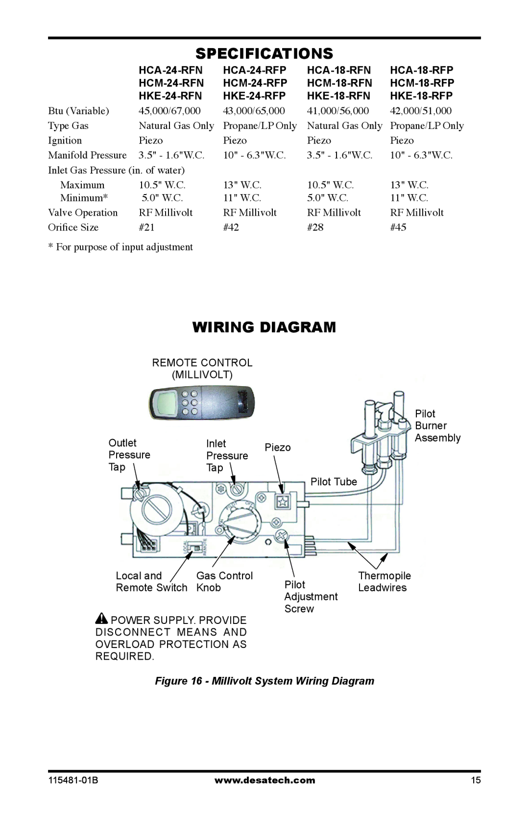
WIRING DIAGRAM
REMOTE CONTROL (MILLIVOLT)
Outlet | Inlet | Piezo | |
Pressure | Pressure | ||
| |||
Tap | Tap |
| |
|
| Pilot Tube |
Pilot
Burner
Assembly
Local and | Gas Control |
Remote Switch | Knob |
POWER SUPPLY. PROVIDE | |
DISCONNECT MEANS AND | |
OVERLOAD PROTECTION AS | |
REQUIRED. |
|
Pilot | Thermopile | |
Leadwires | ||
Adjustment | ||
| ||
Screw |
|
Figure 16 - Millivolt System Wiring Diagram
www.desatech.com | 15 |