ATTACHING THE STAND TO THE MOTOR/BLOWER ASSEMBLY
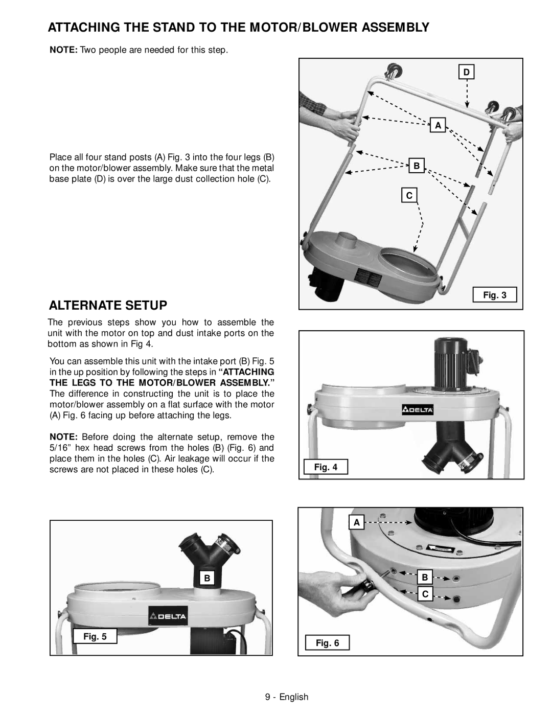
NOTE: Two people are needed for this step.
Place all four stand posts (A) Fig. 3 into the four legs (B) on the motor/blower assembly. Make sure that the metal base plate (D) is over the large dust collection hole (C).
D
![]() A
A
![]() B
B
C
ALTERNATE SETUP
Fig. 3
The previous steps show you how to assemble the unit with the motor on top and dust intake ports on the bottom as shown in Fig 4.
You can assemble this unit with the intake port (B) Fig. 5 in the up position by following the steps in “ATTACHING
THE LEGS TO THE MOTOR/BLOWER ASSEMBLY.” The difference in constructing the unit is to place the motor/blower assembly on a flat surface with the motor
(A) Fig. 6 facing up before attaching the legs.
NOTE: Before doing the alternate setup, remove the 5/16” hex head screws from the holes (B) (Fig. 6) and place them in the holes (C). Air leakage will occur if the screws are not placed in these holes (C).
B
Fig. 4
A ![]()
![]()
B
C
Fig. 5
Fig. 6