safe distance from the cutting wheel, lower the head of the saw slowly into the tile. Cut into the tile up to the edge of the mark without overcutting.
7.Repeat the process on each outline without overcut- ting.
8.Turn the tile over. Repeat steps 2 and 3, overcutting along the lines which will allow the piece to fall out. NOTE: The corners may need to be trimmed with tile nippers (not included with the saw).
9.Turn off the saw.
MITER CUTS: 22.5˚ AND 45˚
Miter cuts are used for cutting outside and inside corners on tile, decorative chair rail and base molding.
The cutting head of the saw is adjustable to three posi- tions: 0˚, 22.5˚ or 45˚. The three grooves (Y) in the cutting cart allow for the cutting head to be set at the three settings without cutting into the cutting cart assembly (H).
1.Loosen the bevel lock knob (CC) in the rear of the saw and adjust the head of the saw to the correct miter degree. The bevel pointer (DD) on the front of the saw will show the angle of adjustment.
2.Always do a dry run and push the cart past the cutting wheel before turning on the saw. Ensure the cutting wheel is adjusted to the center of the groove.
3.Mark the tile and line the tile against the fence of the cutting cart and the edge guide. Proceed to make the cut.
4.Turn off the saw.
MOVING THE SAW
![]() CAUTION: Do not attempt to move the saw while filled with water or personal injury may result.
CAUTION: Do not attempt to move the saw while filled with water or personal injury may result.
Before moving the saw, be sure the to drain the water pan by placing a 5 gallon bucket under the drain plug of the saw. Remove the drain plug and allow the water to empty into the bucket.
Adjustments (Fig. 15–17)
![]() CAUTION: Turn off and unplug the tool before mak- ing any adjustments or removing or installing attach- ments or accessories. Be sure the switch is in the OFF position.
CAUTION: Turn off and unplug the tool before mak- ing any adjustments or removing or installing attach- ments or accessories. Be sure the switch is in the OFF position.
CUTTING CART SCALE
1.Unplug the saw.
2.Move the cart so the cutting wheel is near the cart fence. (X).
3.Using a tape measure or scale, check the scale on the cart.
4.If the scale is in error, loosen the two screws (EE) that hold the scale (FF) in place, adjust to the correct dimension and tighten the screws.
CUTTING WHEEL SQUARE TO CART
1.Place a 90˚ square on the cutting cart.
2.If the gap is not consistent, loosen the bevel lock knob (CC) and adjust the 0˚ bevel adjustment screw (GG)
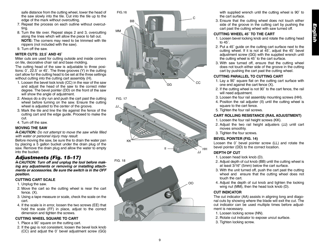
FIG.16
BB
MM
FIG. 17 |
JJ |
KK
FIG. 18
|
|
|
|
|
| with supplied wrench until the cutting wheel is 90˚ to |
|
|
| C |
|
| the cart surface. |
|
|
|
| 3. | Ensure that the cutting wheel does not touch either | |
|
|
|
|
| ||
|
|
|
|
|
| side of the groove in the cutting cart by pushing the |
|
|
|
|
|
| cart past the cutting wheel with saw turned off. |
|
|
|
|
| CUTTING WHEEL 45˚ TO THE CART | |
|
|
|
|
| 1. | Loosen bevel locking knob and rotate the cutting head |
|
|
|
|
|
| to 45˚. |
|
|
|
|
| 2. | Put a 45˚ guide on the cutting cart surface next to the |
|
|
|
|
|
| cutting wheel. If it is not at 45˚, adjust the 45˚ bevel |
|
|
|
|
|
| adjustment screw (GG) with the supplied wrench until |
|
|
|
|
|
| the cutting wheel is 45˚ to the cart surface. |
|
|
|
|
|
| |
|
|
|
|
| 3. | With saw turned off, ensure that the cutting wheel |
|
|
|
|
| ||
|
|
|
|
|
| does not touch either side of the groove in the cutting |
|
|
|
|
|
| cart by pushing the cart past the cutting wheel. |
|
|
|
|
| CUTTING PARALLEL TO CUTTING CART | |
|
|
|
| CC | 1. | Lay a 90˚ square flat on the cutting cart surface with |
GG |
|
|
|
| one end against the cart fence (X). | |
|
|
|
|
| ||
2.If the cutting wheel is not 90˚ to the cart fence, the rail will need adjustment.
3.Loosen the four rail assembly mounting screws (HH).
4.Position the rail adjuster (II) until the cutting wheel is square to the cart fence.
|
| 5. | Tighten the four rail screws. |
|
| CART ROLLING RESISTANCE (RAIL ADJUSTMENT) | |
|
| 1. | Loosen the four rail height screws (KK). |
|
| 2. | Adjust the two rail height adjusters (JJ) until cart |
|
|
| moves smoothly. |
|
| 3. | Tighten the four screws. |
|
| BEVEL POINTER (FIG. 14) | |
|
| Loosen the 0˚ bevel pointer screw (LL) and rotate the | |
II | HH | bevel pointer (DD) to the correct location. | |
|
| ||
JJ |
| DEPTH OF CUT | |
1.Loosen head lock knob (D).
2.Adjust depth of cut knob (BB) until the cutting wheel is at least 3/16" (5mm) below the cart surface.
3.With the unit turned off, push the cart past the cutting wheel and ensure that the cutting wheel does not touch the cart.
OO4. Adjust the depth of cut knob and tighten the locking wing nut (MM), then the head lock knob (D).
CUT INDICATOR
The cut indicator (AA) assists in aligning long and diago- nal cuts by showing where the blade will exit the cut. The cut indicator can be used multiple times before adjust- ment is necessary.
1.Loosen locking screw (NN).
2.Rotate cut indicator to expose uncut surface.
3. Tighten locking screw.
English
9