and adjust to the zero indicator mark. The saw is now adjusted to accurately indicate the depth of cut for the blade used.
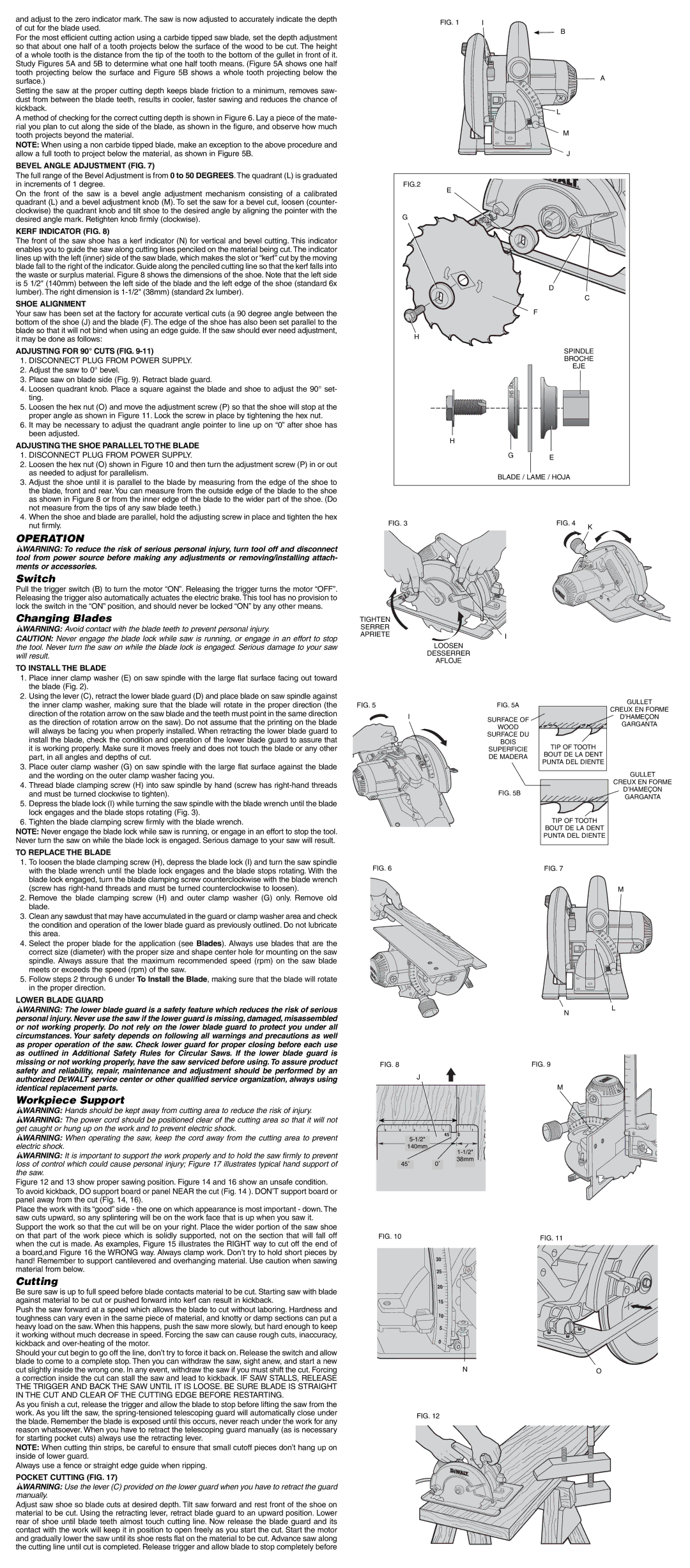
For the most efficient cutting action using a carbide tipped saw blade, set the depth adjustment so that about one half of a tooth projects below the surface of the wood to be cut. The height of a whole tooth is the distance from the tip of the tooth to the bottom of the gullet in front of it. Study Figures 5A and 5B to determine what one half tooth means. (Figure 5A shows one half tooth projecting below the surface and Figure 5B shows a whole tooth projecting below the surface.)
Setting the saw at the proper cutting depth keeps blade friction to a minimum, removes saw- dust from between the blade teeth, results in cooler, faster sawing and reduces the chance of kickback.
A method of checking for the correct cutting depth is shown in Figure 6. Lay a piece of the mate- rial you plan to cut along the side of the blade, as shown in the figure, and observe how much tooth projects beyond the material.
NOTE: When using a non carbide tipped blade, make an exception to the above procedure and allow a full tooth to project below the material, as shown in Figure 5B.
BEVEL ANGLE ADJUSTMENT (FIG. 7)
The full range of the Bevel Adjustment is from 0 to 50 DEGREES. The quadrant (L) is graduated in increments of 1 degree.
On the front of the saw is a bevel angle adjustment mechanism consisting of a calibrated quadrant (L) and a bevel adjustment knob (M). To set the saw for a bevel cut, loosen (counter- clockwise) the quadrant knob and tilt shoe to the desired angle by aligning the pointer with the desired angle mark. Retighten knob firmly (clockwise).
KERF INDICATOR (FIG. 8)
The front of the saw shoe has a kerf indicator (N) for vertical and bevel cutting. This indicator enables you to guide the saw along cutting lines penciled on the material being cut. The indicator lines up with the left (inner) side of the saw blade, which makes the slot or “kerf” cut by the moving blade fall to the right of the indicator. Guide along the penciled cutting line so that the kerf falls into the waste or surplus material. Figure 8 shows the dimensions of the shoe. Note that the left side is 5 1/2" (140mm) between the left side of the blade and the left edge of the shoe (standard 6x lumber). The right dimension is
SHOE ALIGNMENT
Your saw has been set at the factory for accurate vertical cuts (a 90 degree angle between the bottom of the shoe (J) and the blade (F). The edge of the shoe has also been set parallel to the blade so that it will not bind when using an edge guide. If the saw should ever need adjustment, it may be done as follows:
ADJUSTING FOR 90° CUTS (FIG. 9-11)
1.DISCONNECT PLUG FROM POWER SUPPLY.
2.Adjust the saw to 0° bevel.
3.Place saw on blade side (Fig. 9). Retract blade guard.
4.Loosen quadrant knob. Place a square against the blade and shoe to adjust the 90° set- ting.
5.Loosen the hex nut (O) and move the adjustment screw (P) so that the shoe will stop at the proper angle as shown in Figure 11. Lock the screw in place by tightening the hex nut.
6.It may be necessary to adjust the quadrant angle pointer to line up on “0” after shoe has been adjusted.
ADJUSTING THE SHOE PARALLEL TO THE BLADE
1.DISCONNECT PLUG FROM POWER SUPPLY.
2.Loosen the hex nut (O) shown in Figure 10 and then turn the adjustment screw (P) in or out as needed to adjust for parallelism.
3.Adjust the shoe until it is parallel to the blade by measuring from the edge of the shoe to the blade, front and rear. You can measure from the outside edge of the blade to the shoe as shown in Figure 8 or from the inner edge of the blade to the wider part of the shoe. (Do not measure from the tips of any saw blade teeth.)
4.When the shoe and blade are parallel, hold the adjusting screw in place and tighten the hex nut firmly.
OPERATION
![]() WARNING: To reduce the risk of serious personal injury, turn tool off and disconnect tool from power source before making any adjustments or removing/installing attach- ments or accessories.
WARNING: To reduce the risk of serious personal injury, turn tool off and disconnect tool from power source before making any adjustments or removing/installing attach- ments or accessories.
Switch
Pull the trigger switch (B) to turn the motor “ON”. Releasing the trigger turns the motor “OFF”. Releasing the trigger also automatically actuates the electric brake. This tool has no provision to lock the switch in the “ON” position, and should never be locked “ON” by any other means.
Changing Blades
![]() WARNING: Avoid contact with the blade teeth to prevent personal injury.
WARNING: Avoid contact with the blade teeth to prevent personal injury.
CAUTION: Never engage the blade lock while saw is running, or engage in an effort to stop the tool. Never turn the saw on while the blade lock is engaged. Serious damage to your saw will result.
TO INSTALL THE BLADE
1.Place inner clamp washer (E) on saw spindle with the large flat surface facing out toward the blade (Fig. 2).
2.Using the lever (C), retract the lower blade guard (D) and place blade on saw spindle against the inner clamp washer, making sure that the blade will rotate in the proper direction (the direction of the rotation arrow on the saw blade and the teeth must point in the same direction as the direction of rotation arrow on the saw). Do not assume that the printing on the blade will always be facing you when properly installed. When retracting the lower blade guard to install the blade, check the condition and operation of the lower blade guard to assure that it is working properly. Make sure it moves freely and does not touch the blade or any other part, in all angles and depths of cut.
3.Place outer clamp washer (G) on saw spindle with the large flat surface against the blade and the wording on the outer clamp washer facing you.
4.Thread blade clamping screw (H) into saw spindle by hand (screw has
5.Depress the blade lock (I) while turning the saw spindle with the blade wrench until the blade lock engages and the blade stops rotating (Fig. 3).
6.Tighten the blade clamping screw firmly with the blade wrench.
NOTE: Never engage the blade lock while saw is running, or engage in an effort to stop the tool. Never turn the saw on while the blade lock is engaged. Serious damage to your saw will result.
TO REPLACE THE BLADE
1. To loosen the blade clamping screw (H), depress the blade lock (I) and turn the saw spindle |
with the blade wrench until the blade lock engages and the blade stops rotating. With the |
blade lock engaged, turn the blade clamping screw counterclockwise with the blade wrench |
FIG. 1 | I |
|
|
|
| B |
|
|
|
| A |
|
| L |
|
|
| M |
|
|
| J |
|
FIG.2 |
|
|
|
E |
|
|
|
G |
|
|
|
|
| D |
|
|
|
| C |
|
| F |
|
H |
|
|
|
|
| SPINDLE | |
|
| BROCHE | |
|
| EJE | |
H |
|
|
|
| G | E |
|
|
|
| |
| BLADE / LAME / HOJA |
| |
FIG. 3 |
| FIG. 4 | K |
|
|
| |
TIGHTEN |
|
|
|
SERRER |
|
|
|
APRIETE | I |
|
|
|
|
| |
LOOSEN |
|
|
|
DESSERRER |
|
|
|
AFLOJE |
|
|
|
FIG. 5 | FIG. 5A | GULLET | |
CREUX EN FORME | |||
I |
| ||
SURFACE OF | D’HAMEÇON | ||
| GARGANTA | ||
| WOOD | ||
|
| ||
| SURFACE DU |
| |
| BOIS | TIP OF TOOTH | |
| SUPERFICIE | ||
| BOUT DE LA DENT | ||
| DE MADERA | ||
| PUNTA DEL DIENTE | ||
|
| ||
|
| GULLET | |
|
| CREUX EN FORME | |
| FIG. 5B | D’HAMEÇON | |
| GARGANTA | ||
|
| ||
|
| TIP OF TOOTH | |
|
| BOUT DE LA DENT | |
|
| PUNTA DEL DIENTE | |
FIG. 6 |
| FIG. 7 |
| (screw has |
2. | Remove the blade clamping screw (H) and outer clamp washer (G) only. Remove old |
| blade. |
3. | Clean any sawdust that may have accumulated in the guard or clamp washer area and check |
| the condition and operation of the lower blade guard as previously outlined. Do not lubricate |
| this area. |
4. | Select the proper blade for the application (see Blades). Always use blades that are the |
| correct size (diameter) with the proper size and shape center hole for mounting on the saw |
| spindle. Always assure that the maximum recommended speed (rpm) on the saw blade |
| meets or exceeds the speed (rpm) of the saw. |
5. | Follow steps 2 through 6 under To Install the Blade, making sure that the blade will rotate |
| in the proper direction. |
LOWER BLADE GUARD
![]() WARNING: The lower blade guard is a safety feature which reduces the risk of serious personal injury. Never use the saw if the lower guard is missing, damaged, misassembled or not working properly. Do not rely on the lower blade guard to protect you under all circumstances. Your safety depends on following all warnings and precautions as well as proper operation of the saw. Check lower guard for proper closing before each use as outlined in Additional Safety Rules for Circular Saws. If the lower blade guard is missing or not working properly, have the saw serviced before using. To assure product safety and reliability, repair, maintenance and adjustment should be performed by an authorized DEWALT service center or other qualified service organization, always using identical replacement parts.
WARNING: The lower blade guard is a safety feature which reduces the risk of serious personal injury. Never use the saw if the lower guard is missing, damaged, misassembled or not working properly. Do not rely on the lower blade guard to protect you under all circumstances. Your safety depends on following all warnings and precautions as well as proper operation of the saw. Check lower guard for proper closing before each use as outlined in Additional Safety Rules for Circular Saws. If the lower blade guard is missing or not working properly, have the saw serviced before using. To assure product safety and reliability, repair, maintenance and adjustment should be performed by an authorized DEWALT service center or other qualified service organization, always using identical replacement parts.
Workpiece Support
![]() WARNING: Hands should be kept away from cutting area to reduce the risk of injury.
WARNING: Hands should be kept away from cutting area to reduce the risk of injury.
![]() WARNING: The power cord should be positioned clear of the cutting area so that it will not get caught or hung up on the work and to prevent electric shock.
WARNING: The power cord should be positioned clear of the cutting area so that it will not get caught or hung up on the work and to prevent electric shock.
![]() WARNING: When operating the saw, keep the cord away from the cutting area to prevent electric shock.
WARNING: When operating the saw, keep the cord away from the cutting area to prevent electric shock.
![]() WARNING: It is important to support the work properly and to hold the saw firmly to prevent loss of control which could cause personal injury; Figure 17 illustrates typical hand support of the saw.
WARNING: It is important to support the work properly and to hold the saw firmly to prevent loss of control which could cause personal injury; Figure 17 illustrates typical hand support of the saw.
Figure 12 and 13 show proper sawing position. Figure 14 and 16 show an unsafe condition. To avoid kickback, DO support board or panel NEAR the cut (Fig. 14 ). DON’T support board or panel away from the cut (Fig. 14, 16).
Place the work with its “good” side - the one on which appearance is most important - down. The saw cuts upward, so any splintering will be on the work face that is up when you saw it. Support the work so that the cut will be on your right. Place the wider portion of the saw shoe on that part of the work piece which is solidly supported, not on the section that will fall off when the cut is made. As examples, Figure 15 illustrates the RIGHT way to cut off the end of a board,and Figure 16 the WRONG way. Always clamp work. Don’t try to hold short pieces by hand! Remember to support cantilevered and overhanging material. Use caution when sawing material from below.
Cutting
Be sure saw is up to full speed before blade contacts material to be cut. Starting saw with blade against material to be cut or pushed forward into kerf can result in kickback.
Push the saw forward at a speed which allows the blade to cut without laboring. Hardness and toughness can vary even in the same piece of material, and knotty or damp sections can put a heavy load on the saw. When this happens, push the saw more slowly, but hard enough to keep it working without much decrease in speed. Forcing the saw can cause rough cuts, inaccuracy, kickback and
N
FIG. 8 | FIG. 9 |
|
|
J
M
140mm![]()
38mm
45˚ 0˚
FIG. 10 | FIG. 11 |
M
L
Should your cut begin to go off the line, don’t try to force it back on. Release the switch and allow blade to come to a complete stop. Then you can withdraw the saw, sight anew, and start a new cut slightly inside the wrong one. In any event, withdraw the saw if you must shift the cut. Forcing a correction inside the cut can stall the saw and lead to kickback. IF SAW STALLS, RELEASE THE TRIGGER AND BACK THE SAW UNTIL IT IS LOOSE. BE SURE BLADE IS STRAIGHT IN THE CUT AND CLEAR OF THE CUTTING EDGE BEFORE RESTARTING.
As you finish a cut, release the trigger and allow the blade to stop before lifting the saw from the work. As you lift the saw, the
NOTE: When cutting thin strips, be careful to ensure that small cutoff pieces don’t hang up on inside of lower guard.
Always use a fence or straight edge guide when ripping.
POCKET CUTTING (FIG. 17)
![]() WARNING: Use the lever (C) provided on the lower guard when you have to retract the guard manually.
WARNING: Use the lever (C) provided on the lower guard when you have to retract the guard manually.
Adjust saw shoe so blade cuts at desired depth. Tilt saw forward and rest front of the shoe on material to be cut. Using the retracting lever, retract blade guard to an upward position. Lower rear of shoe until blade teeth almost touch cutting line. Now release the blade guard and its contact with the work will keep it in position to open freely as you start the cut. Start the motor and gradually lower the saw until its shoe rests flat on the material to be cut. Advance saw along the cutting line until cut is completed. Release trigger and allow blade to stop completely before
NO
FIG. 12