COMPONENTS (Fig. 1)
![]() WARNING: Never modify the power tool or any part of it. Damage or personal injury could result.
WARNING: Never modify the power tool or any part of it. Damage or personal injury could result.
A. Variable speed trigger | E. Accessory side mount |
B. LED worklight | F. Cut guide block |
C. Accessory clamp lever | G. Cut guide arm |
D. |
|
INTENDED USE
This oscillating
DO NOT use under wet conditions or in presence of flammable liquids or gases.
This oscillating
ASSEMBLY AND ADJUSTMENTS
![]() WARNING: To reduce the risk of injury, turn unit off and disconnect it from power source before installing and removing accessories, before adjusting or when making repairs. An accidental
WARNING: To reduce the risk of injury, turn unit off and disconnect it from power source before installing and removing accessories, before adjusting or when making repairs. An accidental
![]() WARNING: Risk of lacerations or burns. Do not touch the sharp edges of accessories at any time. Do not touch workpiece or blade immediately after operating the tool. They can become very hot. Handle carefully. Always allow accessories and workpiece to cool before handling.
WARNING: Risk of lacerations or burns. Do not touch the sharp edges of accessories at any time. Do not touch workpiece or blade immediately after operating the tool. They can become very hot. Handle carefully. Always allow accessories and workpiece to cool before handling.
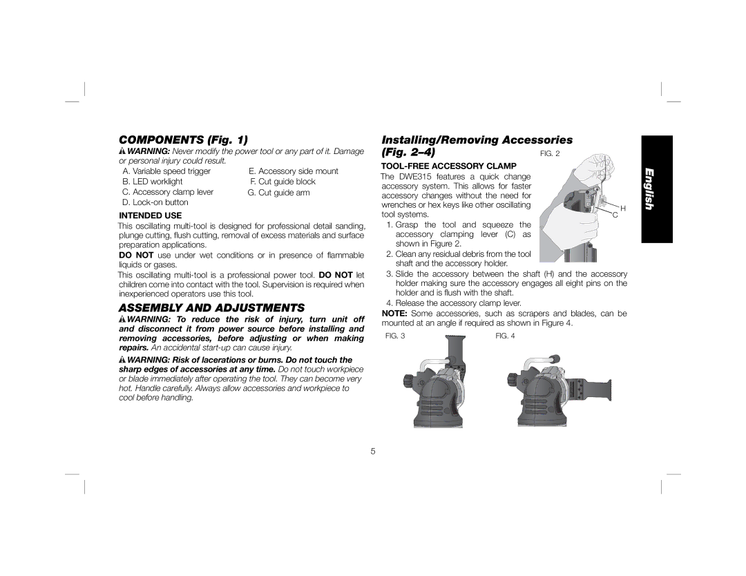
Installing/Removing Accessories
(Fig. | FIG. 2 | |
|
| |
The DWE315 features a quick change |
| |
accessory system. This allows for faster |
| |
accessory changes without the need for |
| |
wrenches or hex keys like other oscillating | H | |
tool systems. | ||
C |
1. Grasp the tool and squeeze the accessory clamping lever (C) as shown in Figure 2.
2. Clean any residual debris from the tool shaft and the accessory holder.
3.Slide the accessory between the shaft (H) and the accessory holder making sure the accessory engages all eight pins on the holder and is flush with the shaft.
4.Release the accessory clamp lever.
NOTE: Some accessories, such as scrapers and blades, can be mounted at an angle if required as shown in Figure 4.
FIG. 3 | FIG. 4 |
English
5