PM12-EC PM12-EL
62500230
All Rights Reserved
Copyright
Trademarks
FCC and DOC Statement on Class B
Mainboard
Table of Contents
Appendix B System Error Messages
Appendix C Troubleshooting
Supported Softwares
Function
Features and Specifications
Features
Chipset
Processor
Onboard Audio Features
Onboard LAN Features PM12-EL only
Onboard Graphics Features
Introduction
Rear Panel I/O Ports PC 99 color-coded connectors
Connectors
PCI Bus Master IDE Controller
IrDA Interface
USB Ports
Desktop Management Interface DMI
Dual Function Power Button
Introduction Intelligence
Wake-On-Ring
Wake-On-LAN
Wake-On-USB Keyboard/Mouse
RTC Timer to Power-on the System
Wake-On-PS/2 Keyboard/Mouse
AC Power Failure Recovery
Virus Protection
Package Checklist
Mainboard Layout
PM12-EC
Hardware Installation
Supports onboard LAN
System Memory
DDR
Hardware Installation Installing the DIM Module
Jumper Settings for Clearing Cmos Data
JP1
Hardware Installation
On VCC power
Jumper Settings for Selecting the PS/2 Power
PS/2 power select
Rear Panel I/O Ports
Hardware Installation 1 PS/2 Mouse and PS/2 Keyboard Ports
J11
PS/2 Mouse PS/2 Keyboard
Accordingly. Refer to for more information
Hardware Installation 2 RJ45 Fast-Ethernet Port PM12-EL only
Additional USB Ports USB 3 and USB Pin Function
Hardware Installation Universal Serial Bus Ports
USB 3 and USB J13
Hardware Installation
Connecting the Serial Ports
Serial Ports
Hardware Installation Parallel Port
Standard Parallel Port One direction only
Allows parallel port to operate
Rate
VGA Port
Hardware Installation VGA Port
VGA1
Game/MIDI Port
Hardware Installation 2.5.7 Game/MIDI Port
CN301
Hardware Installation Audio Jacks
Line-out Line-in Mic-in Front audio J21 Front Audio J21
Onboard Audio Jacks
Front Audio J21
I/O Connectors
Internal Audio Connectors
J19
J18 Pin
FDD J6
Hardware Installation 2.6.2 Floppy Disk Drive Connector
Connecting the Floppy Disk Drive Cable
Hardware Installation IDE Disk Drive Connector
Connecting the IDE Disk Drive Cable
Adding a Second IDE Disk Drive
Hardware Installation IrDA Connector
IrDA J8
Hardware Installation 2.6.5 CPU Fan Connector
J15
Hardware Installation Chassis Fan Connector
J14
+5VSB Ground
Hardware Installation 2.6.7 Wake-On-LAN Connector
Wake-On-LAN
Hardware Installation Wake-On-Ring Connector
Wake-On-Ring
Hardware Installation 2.6.9 LEDs
Dimm Standby Power LED PCI Standby
Dimm Standby Power LED
PCI Standby Power LED
Hardware Installation Power Connectors
J17
Ground +5V
ATX Main Power Connector Pin Function 12V Ground +5V
+12V +5V +12V Power Connector Pin Function Ground
Front panel Connectors J10
PWR-LED Power/Standby LED
Basic Input/Output System
Standard Cmos Features
When you press Del, the main menu screen will appear
Time
Award Bios Setup Utility
Date
Access Mode
IDE HDD Auto Detection
IDE Primary Master/Slave and IDE Secondary Master/Slave
Capacity
Cylinder
Head
Precomp
Landing Zone
Halt On
Base Memory
Extended Memory
Total Memory
Award Bios Setup Utility Advanced Bios Features
Virus Warning
Quick Power On Self Test
CPU L1 & L2 Cache
CPU L2 Cache ECC Checking
Swap Floppy Drive
Boot Up Floppy Seek
Boot Up NumLock Status
Typematic Rate Setting
Typematic Delay Msec
OS Select for Dram 64MB
Video Bios Shadow
Security Option
Award Bios Setup Utility Advanced Chipset Features
Dram Clock/Drive Control
Current FSB Frequency
Current Dram Frequency
Dram Clock
Dram Command Rate
Dram Timing
Sdram CAS Latency
Bank Interleave
AGP Mode
AGP & P2P Bridge Control
AGP Aperture Size
AGP Driving Control
Select Enabled to support the AGP Fast Write function
AGP Driving Value
AGP Fast Write
AGP Master 1 WS Write
PCI Delay Transaction
CPU & PCI Bus Control
CPU to PCI Write Buffer
PCI Master 0 WS Write
System Bios Cacheable
Memory Hole
Video RAM Cacheable
VGA Share Memory Size
Award Bios Setup Utility Integrated Peripherals
VIA OnChip IDE Device
IDE Primary Master/Slave PIO and IDE Secondary Master/Slave
IDE Prefetch Mode
On-Chip IDE Channel 0 and On-Chip IDE Channel
Onboard LAN Boot ROM PM12-EL only
VIA OnChip PCI Device
Onboard AC97 Audio
Onboard LAN PM12-EL only
Onboard Serial Port 1 and Onboard Serial Port
Super IO Device
Onboard FDC Controller
Uart Mode Select
IR Transmission Delay
UR2 Duplex Mode
Use IR Pins
Parallel Port Mode
EPP Mode Select
ECP Mode Use DMA
Game Port Address
IDE HDD Block Mode
Init Display First
OnChip USB Controller
USB Keyboard Support
Acpi Suspend Type
Award Bios Setup Utility Power Management Setup
Acpi Function
Power Management Option
HDD Power Down
Suspend Mode
Video Off Option
Run Vgabios if S3 Resume
Modem Use IRQ
Soft-Off by Pwrbtn
PWR Lost Resume State
5.12 IRQ/Event Activity Detect
PS2KB Wakeup Select
USB Resume from S3
PCI Master
Resume on PCI Event
Resume On LAN/Ring
Resume Time hhmmss
Resume on Alarm
Date of Month
IRQs Activity Monitoring
IRQ15
Award Bios Setup Utility 6 PnP/PCI Configurations
PNP OS Installed
Reset Configuration Data
Resources Controlled By
IRQ Resources
6.5 PCI/VGA Palette Snoop
Assign IRQ for VGA
Assign IRQ for USB
PCI Slot 1 Use IRQ to PCI Slot 3 Use IRQ
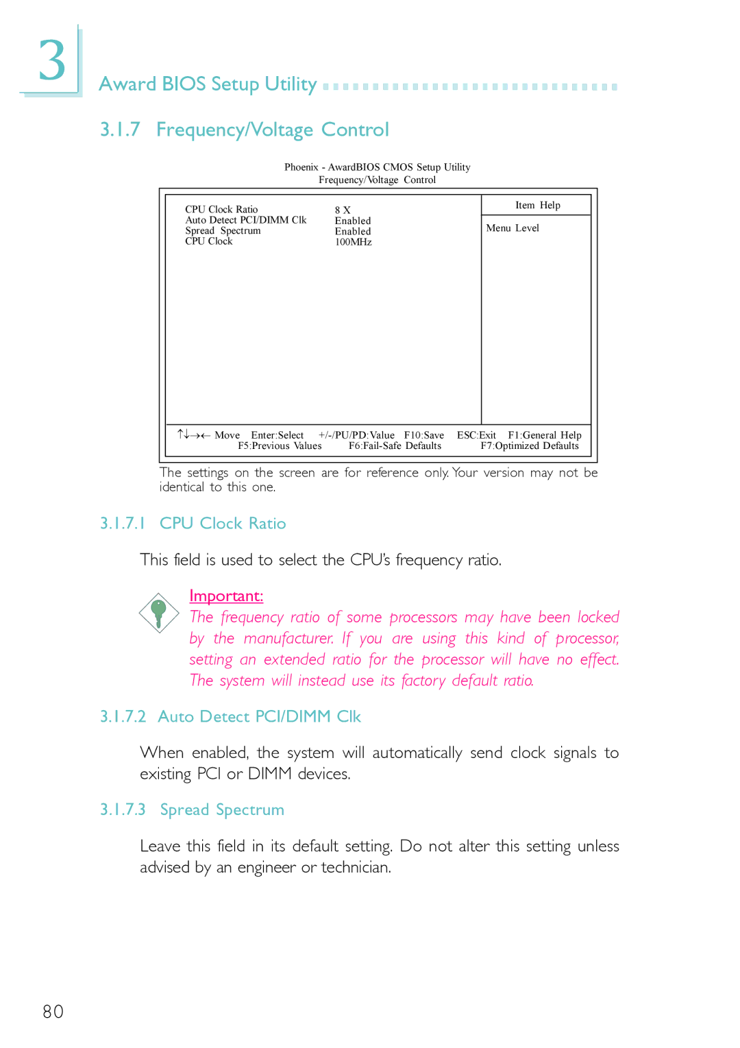
Award Bios Setup Utility Frequency/Voltage Control
CPU Clock Ratio
This field is used to select the CPU’s frequency ratio
Auto Detect PCI/DIMM Clk
CPU Clock
Award Bios Setup Utility Load Fail-Safe Defaults
Load Optimized Defaults
Award Bios Setup Utility Set Supervisor Password
Set User Password
Award Bios Setup Utility Save & Exit Setup
Exit Without Saving
Updating the Bios
Award Bios Setup Utility
Desktop Management Interface DMI
Running the DMI Utility
Supported Software Using the DMI Utility
Edit DMI
Save DMI File
Supported Software Add DMI
Load DMI File
Drivers, Utilities and Software Applications
Supported Software
Supported Software VIA Service Pack
VIA Service Pack Installation Notes
Supported Software
Supported Software 2 S3 ProSavage VGA Drivers
Supported Software Realtek Audio Drivers
Supported Software VIA LAN Drivers PM12-EL only
Supported Software VIA USB 2.0 Drivers
Supported Software 4.2.6 Microsoft DirectX
Supported Software McAfee VirusScan Online
Installation Notes
Appendix a Using the Suspend to RAM Function
Using the Suspend to RAM Function