A B O U T T H E D E V E L O P M E N T B O A R D
Switches and reset functionality
S w i t c h e s a n d r e s e t f u n c t i o n a l i t y
. . . . . . . . . . . . . . . . . . . . . . . . . . . . . . . . . . . . . . . . . . . . . . . . . . . . . . . . . . . . . . . . . . . . . . . . . . . . . . . . . .
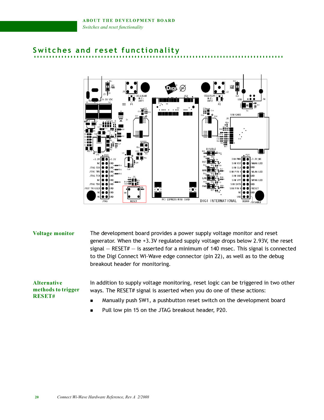
Voltage monitor The development board provides a power supply voltage monitor and reset generator. When the +3.3V regulated supply voltage drops below 2.93V, the reset signal — RESET# — is asserted for a minimum of 140 msec. This signal is connected to the Digi Connect
Alternative methods to trigger
RESET#
In addition to supply voltage monitoring, reset logic can be triggered in two other ways. The RESET# signal is asserted when you do one of these actions:
Manually push SW1, a pushbutton reset switch on the development board
Pull low pin 15 on the JTAG breakout header, P20.
20 | Connect |