Appendix A
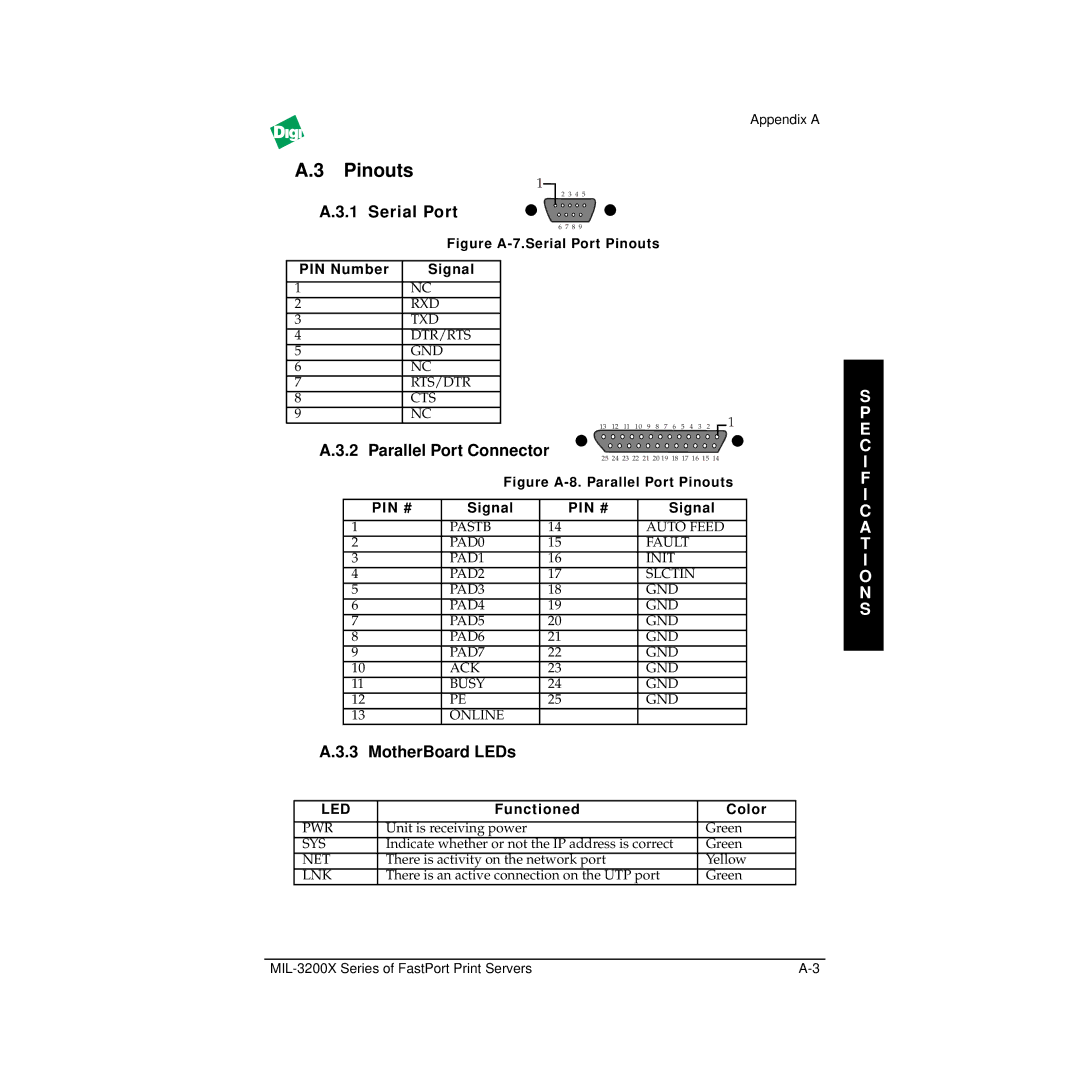
A.3 Pinouts
1
2 3 4 5
| A.3.1 | Serial Port |
|
|
|
|
|
|
|
|
|
|
|
|
|
|
|
|
|
|
| ||||||
|
|
|
|
|
|
|
|
| 6 | 7 | 8 | 9 |
|
|
|
|
|
|
|
|
|
|
|
|
|
|
|
|
|
|
|
|
|
| Figure |
|
|
|
|
|
|
|
|
| |||||||||||
|
|
|
|
|
|
|
|
|
|
|
|
|
|
|
|
|
|
|
|
|
|
|
|
|
| ||
| PIN Number |
| Signal |
|
|
|
|
|
|
|
|
|
|
|
|
|
|
|
|
|
|
|
| ||||
|
|
|
|
|
|
|
|
|
|
|
|
|
|
|
|
|
|
|
|
|
|
|
|
|
|
| |
1 |
|
|
| NC |
|
|
|
|
|
|
|
|
|
|
|
|
|
|
|
|
|
|
|
| |||
2 |
|
|
| RXD |
|
|
|
|
|
|
|
|
|
|
|
|
|
|
|
|
|
|
|
| |||
3 |
|
|
| TXD |
|
|
|
|
|
|
|
|
|
|
|
|
|
|
|
|
|
|
|
| |||
4 |
|
|
| DTR/RTS |
|
|
|
|
|
|
|
|
|
|
|
|
|
|
|
|
|
|
|
| |||
5 |
|
|
| GND |
|
|
|
|
|
|
|
|
|
|
|
|
|
|
|
|
|
|
|
| |||
6 |
|
|
| NC |
|
|
|
|
|
|
|
|
|
|
|
|
|
|
|
|
|
|
|
| |||
7 |
|
|
| RTS/DTR |
|
|
|
|
|
|
|
|
|
|
|
|
|
|
|
|
|
|
|
| |||
8 |
|
|
| CTS |
|
|
|
|
|
|
|
|
|
|
|
|
|
|
|
|
|
|
|
| |||
9 |
|
|
| NC |
|
|
|
|
|
|
|
|
|
|
|
|
|
|
|
|
|
|
|
| |||
|
|
|
|
|
|
| 13 | 12 | 11 | 10 | 9 | 8 | 7 | 6 | 5 | 4 | 3 | 2 | 1 |
|
| ||||||
| A.3.2 | Parallel Port Connector |
|
|
|
| |||||||||||||||||||||
|
|
| 25 | 24 | 23 | 22 | 21 | 20 19 | 18 | 17 | 16 | 15 | 14 |
|
| ||||||||||||
|
|
|
|
|
|
|
|
|
|
|
|
|
| ||||||||||||||
|
|
|
|
|
|
|
| Figure | |||||||||||||||||||
|
|
|
|
|
|
|
|
|
|
|
|
|
|
|
|
|
|
|
|
| |||||||
|
|
| PIN # |
| Signal |
| PIN # |
|
|
|
|
|
|
| Signal |
| |||||||||||
|
|
|
|
|
|
|
|
|
|
|
|
|
|
|
|
|
|
|
| ||||||||
|
| 1 |
|
|
|
| PASTB | 14 |
|
|
|
|
|
|
| AUTO FEED |
| ||||||||||
|
| 2 |
|
|
|
| PAD0 | 15 |
|
|
|
|
|
|
| FAULT |
|
|
|
|
|
| |||||
|
| 3 |
|
|
|
| PAD1 | 16 |
|
|
|
|
|
|
| INIT |
|
|
|
|
|
|
| ||||
|
| 4 |
|
|
|
| PAD2 | 17 |
|
|
|
|
|
|
| SLCTIN |
|
|
|
|
| ||||||
|
| 5 |
|
|
|
| PAD3 | 18 |
|
|
|
|
|
|
| GND |
|
|
|
|
|
|
| ||||
|
| 6 |
|
|
|
| PAD4 | 19 |
|
|
|
|
|
|
| GND |
|
|
|
|
|
|
| ||||
|
| 7 |
|
|
|
| PAD5 | 20 |
|
|
|
|
|
|
| GND |
|
|
|
|
|
|
| ||||
|
| 8 |
|
|
|
| PAD6 | 21 |
|
|
|
|
|
|
| GND |
|
|
|
|
|
|
| ||||
|
| 9 |
|
|
|
| PAD7 | 22 |
|
|
|
|
|
|
| GND |
|
|
|
|
|
|
| ||||
|
| 10 |
|
|
|
| ACK | 23 |
|
|
|
|
|
|
| GND |
|
|
|
|
|
|
| ||||
|
| 11 |
|
|
|
| BUSY | 24 |
|
|
|
|
|
|
| GND |
|
|
|
|
|
|
| ||||
|
| 12 |
|
|
|
| PE | 25 |
|
|
|
|
|
|
| GND |
|
|
|
|
|
|
| ||||
|
| 13 |
|
|
|
| ONLINE |
|
|
|
|
|
|
|
|
|
|
|
|
|
|
|
|
|
|
| |
| A.3.3 MotherBoard LEDs |
|
|
|
|
|
|
|
|
|
|
|
|
|
|
|
|
|
|
| |||||||
|
|
|
|
|
|
|
|
|
|
|
|
|
|
|
|
|
|
|
|
|
| ||||||
| LED |
|
|
|
| Functioned |
|
|
|
|
|
|
|
|
|
|
|
| Color | ||||||||
|
|
|
|
|
|
|
|
|
|
|
|
|
|
|
|
|
|
|
|
| |||||||
| PWR |
| Unit is receiving power |
|
|
|
|
|
|
|
|
|
|
|
|
|
|
| Green | ||||||||
| SYS |
| Indicate whether or not the IP address is correct |
|
|
| Green | ||||||||||||||||||||
| NET |
| There is activity on the network port |
|
|
|
|
|
|
|
|
|
|
| Yellow | ||||||||||||
| LNK |
| There is an active connection on the UTP port |
|
|
|
|
| Green | ||||||||||||||||||
S P E C I F I C A T I O N S