Digi TransPort® WR21 Installation Guide
Step 2) Connect the Cellular (WWAN) Antenna(s): Connect the cellular antenna to the “WWAN PRIMARY” connector (SMA Female) on the unit. If the unit is equipped with a secondary cellular antenna connector (WWAN SECONDARY), it is highly recommended to connect an additional antenna to this connector for diversification. Dual antennas will provide improved signal strength thus better performance.
Note: For most applications, the antenna(s) included with the unit will provide suitable reception, but some circumstances/environments may require a higher quality antenna or one mounted in a different location. If this is the case, Digi has many antenna options to chose from
Step 3) Connect the LAN Cable: Connect one end of the Ethernet cable to the “LAN 0” port on the unit and the other end to a LAN port on a PC.
Step 4) Connect the Serial Cable (optional): Connect one end of the serial cable (not included) to the “SERIAL 0” port on the unit and other end to the serial port on a
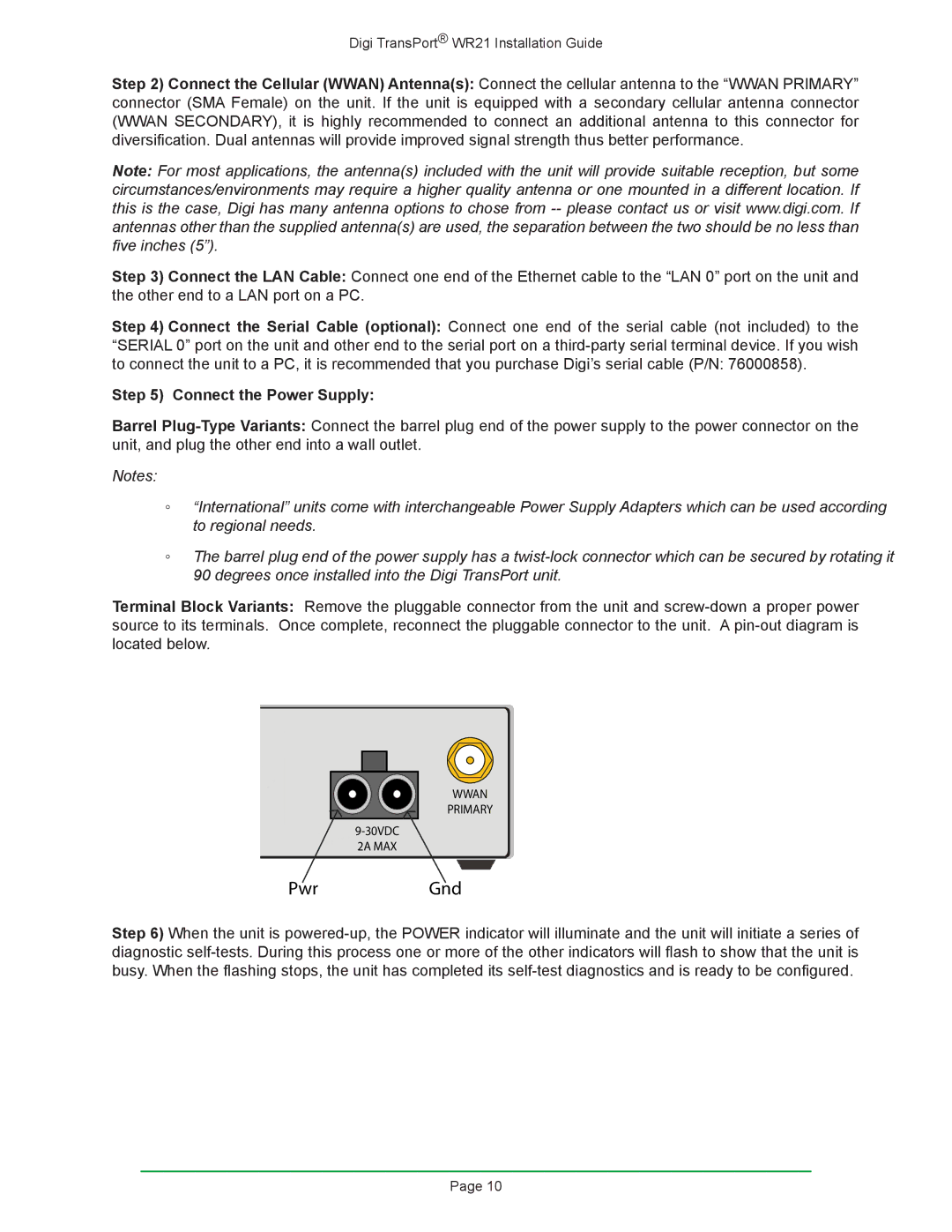
Step 5) Connect the Power Supply:
Barrel
Notes:
◦◦ “International” units come with interchangeable Power Supply Adapters which can be used according to regional needs.
◦◦ The barrel plug end of the power supply has a
Terminal Block Variants: Remove the pluggable connector from the unit and
WWAN PRIMARY
2A MAX
PwrGnd
Step 6) When the unit is
Page 10