A600/4 FRONT PLATE DIAGRAM
20 | 19 | 18 | 17 | 16 | 15 | 14 | 13 | 12 |
|
|
| 11 | 10 | |||
| FREQ |
|
| SUM |
| FREQ | GAIN |
|
| INT | OUTPUT | REAR | FRONT |
|
| |
LP |
| LP |
| REAR | LP |
|
|
| LP |
| EXT | R |
|
| LP |
|
|
|
|
|
|
|
|
|
|
|
| ||||||
|
|
|
|
|
|
|
|
|
|
|
| |||||
| 30 4K |
|
|
|
| 30 | 4K | MIN MAX |
|
|
|
|
|
| FULL | 30 4K |
FULL | HP | FULL | HP |
| FULL | HP |
| REAR | FULL HP |
|
|
|
|
| HP FREQ | |
| OUTPUTS |
|
| SOURCE |
|
|
|
| SOURCE |
|
|
|
|
| ||
|
|
|
|
|
|
|
|
|
|
|
| GAIN |
| |||
|
|
|
|
|
|
|
|
| QBASS ATT |
|
|
|
| |||
| RR- | RR+ | RL+ | RL- | FR- FR+ | REM | FL+ | FL- | 0 | +12dB | L |
|
| MIN MAX |
| |
|
|
| OUT | IN | IN |
|
| |||||||||
|
|
|
| FRONT |
| |||||||||||
| BRIDGED |
|
| BRIDGED |
|
|
|
|
|
| ||||||
|
|
|
|
|
|
|
|
|
|
|
|
| ||||
1 | 2 | 3 | 4 | 5 | 6 | 7 | 8 | 9 |
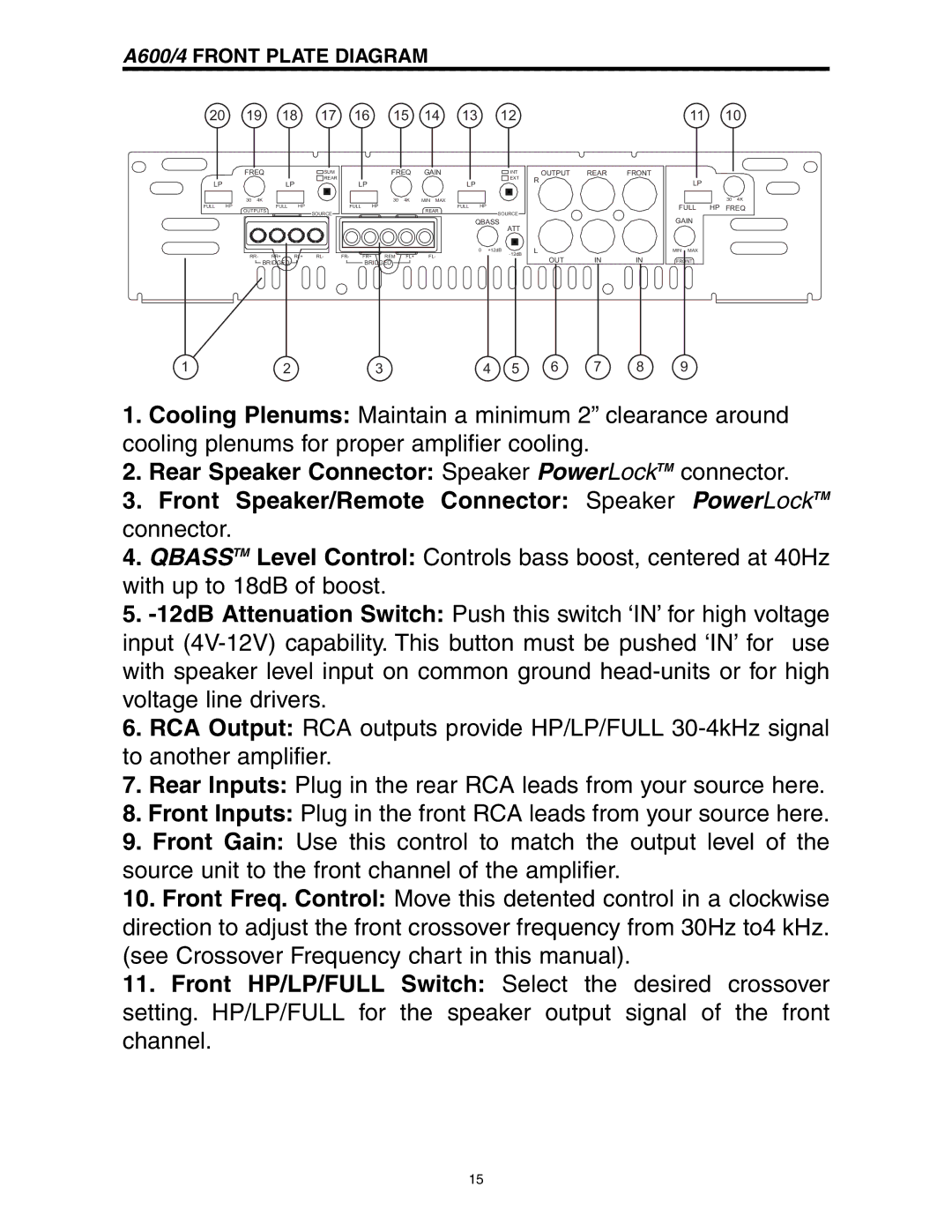
1.Cooling Plenums: Maintain a minimum 2” clearance around cooling plenums for proper amplifier cooling.
2.Rear Speaker Connector: Speaker PowerLockTM connector.
3.Front Speaker/Remote Connector: Speaker PowerLockTM connector.
4.QBASSTM Level Control: Controls bass boost, centered at 40Hz with up to 18dB of boost.
5.
6.RCA Output: RCA outputs provide HP/LP/FULL
7.Rear Inputs: Plug in the rear RCA leads from your source here.
8.Front Inputs: Plug in the front RCA leads from your source here.
9.Front Gain: Use this control to match the output level of the source unit to the front channel of the amplifier.
10.Front Freq. Control: Move this detented control in a clockwise direction to adjust the front crossover frequency from 30Hz to4 kHz. (see Crossover Frequency chart in this manual).
11.Front HP/LP/FULL Switch: Select the desired crossover setting. HP/LP/FULL for the speaker output signal of the front channel.
15