4


WIRING DIAGRAM


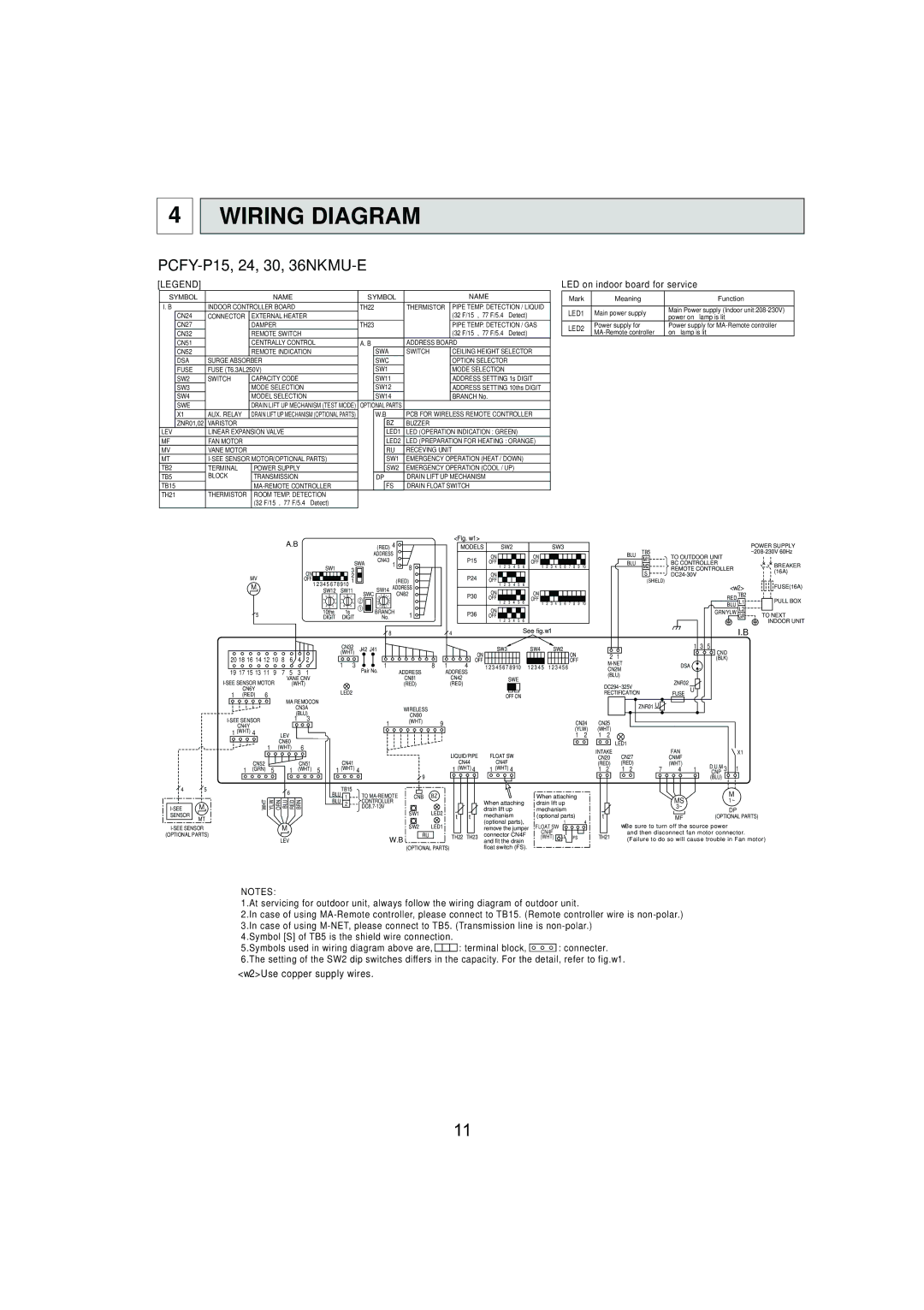
PCFY-P15, 24, 30, 36NKMU-E


[LEGEND]


LED on indoor board for service


SYMBOL


NAME

SYMBOL


NAME


Mark

Meaning

Function


I. B

INDOOR CONTROLLER BOARD

TH22

THERMISTOR


PIPE TEMP. DETECTION / LIQUID


LED1

Main power supply

Main Power supply (Indoor unit:208-230V)


CN24

CONNECTOR


EXTERNAL HEATER


(32°F/15ΚΩ, 77°F/5.4ΚΩ Detect)


power on → lamp is lit


CN27


DAMPER

TH23


PIPE TEMP. DETECTION / GAS


LED2

Power supply for

Power supply for MA-Remote controller


CN32


REMOTE SWITCH


(32°F/15ΚΩ, 77°F/5.4ΚΩ Detect)


MA-Remote controller

on → lamp is lit


CN51


CENTRALLY CONTROL

A. B

ADDRESS BOARD


CN52


REMOTE INDICATION


SWA

SWITCH


CEILING HEIGHT SELECTOR


DSA

SURGE ABSORBER


SWC


OPTION SELECTOR


FUSE

FUSE (T6.3AL250V)


SW1


MODE SELECTION


SW2

SWITCH


CAPACITY CODE


SW11


ADDRESS SETTING 1s DIGIT


SW3


MODE SELECTION


SW12


ADDRESS SETTING 10ths DIGIT


SW4


MODEL SELECTION


SW14


BRANCH No.


SWE


DRAIN LIFT UP MECHANISM (TEST MODE)

OPTIONAL PARTS


X1

AUX. RELAY


DRAIN LIFT UP MECHANISM (OPTIONAL PARTS)


W.B

PCB FOR WIRELESS REMOTE CONTROLLER


ZNR01,02

VARISTOR


BZ

BUZZER


LEV


LINEAR EXPANSION VALVE


LED1

LED (OPERATION INDICATION : GREEN)


MF

FAN MOTOR


LED2

LED (PREPARATION FOR HEATING : ORANGE)


MV

VANE MOTOR


RU

RECEVING UNIT


MT

I-SEE SENSOR MOTOR(OPTIONAL PARTS)


SW1

EMERGENCY OPERATION (HEAT / DOWN)


TB2

TERMINAL

POWER SUPPLY


SW2

EMERGENCY OPERATION (COOL / UP)


TB5

BLOCK

TRANSMISSION


DP

DRAIN LIFT UP MECHANISM


TB15


MA-REMOTE CONTROLLER


FS

DRAIN FLOAT SWITCH


TH21

THERMISTOR

ROOM TEMP. DETECTION


(32°F/15ΚΩ, 77°F/5.4ΚΩ Detect)


A.B


(RED) 4


<Fig. w1>


POWER SUPPLY


MODELS


SW2


SW3


ADDRESS


ON


ON


BLU

TB5

TO OUTDOOR UNIT


~208-230V 60Hz


CN43


P15


M1


SWA


OFF

2

3

4

5

6

OFF

2

3

4

5

6

7

8

9

10

BLU

BC CONTROLLER


BREAKER


SW1


1

8


1

1

M2


3


S

REMOTE CONTROLLER


(16A)


ON


ON


DC24-30V


MV


2


P24


OFF


(RED)

OFF

2

3

4

5

6


(SHIELD)


M

12345678910 1


1


<w2>

FUSE(16A)

SW12

SW11


SW14 ADDRESS


ON


9

0

1

9

0

1


SWC

EF

0123

CN82

P30


ON


RED

TB2


8


2

8


2

2

CD


4


OFF


OFF


PULL BOX


7


3

7


3

B

876

5


1

2

3

4

5

6

1

2

3

4

5

6

7

8

9

10


BLU L1


6

5

4

6

5

4

1

A9


5

10ths

1s


BRANCH

1

P36

ON


GRN/YLW

L2

TO NEXT

DIGIT

DIGIT

No.

OFF

2

3

4

5

6


GR


1


INDOOR UNIT

20 18 16 14 12 10 8 6 4 2

19 17 15 13 11 9 7 5 3 1

I-SEE SENSOR MOTOR

VANE CNV

(WHT)

CN6Y


1 (RED) 6

MA REMOCON


CN3A


(BLU)

I-SEE SENSOR

1

3

CN4Y


1 (WHT) 4

LEV


1

CN60

6

(WHT)


8


4


See fig.w1


CN32

J42 J41


SW3

SW4

SW2


1 3 5

(WHT)


ON


ON


2 1


1

3


OFF


OFF


M-NET


1


8

1

4

12345678910

12345

123456


DSA

ADDRESS


CN2M


Pair No.


ADDRESS


CN81


CN42

SWE


(BLU)


(RED)


(RED)


DC294~325V

ZNR02

LED2


FUSE U


OFF ON


RECTIFICATION


WIRELESS


ZNR01 U


CN90


1

(WHT)


9


CN24

CN25


(YLW)

(WHT)


1

2

1

2


LED1

I.B

CND

(BLK)

45

I-SEE

M

SENSOR

MT


I-SEE SENSOR

(OPTIONAL PARTS)

CN52

5

1

CN51

1 (GRN)

(WHT) 5


6


WHT

YLW ORN

BLU RED

BRN

M

LEV


LIQUID/PIPE

FLOAT SW

INTAKE

CN27


FAN


X1

CN41

CN20


CNMF


CN44

CN4F

(RED)

(RED)


(WHT)


D.U.MCNP 3 1

1 (WHT) 4

1 (WHT) 4

1 (WHT) 4

1 2

1 2

7

4

1


9


(BLU)

BLU

TB15

TO MA-REMOTE

CNB

BZ


When attaching


M

1


MS

BLU

2

CONTROLLER


When attaching

drain lift up


1~


DC8.7-13V

SW1

LED2


drain lift up

mechanism


3~

DP


mechanism

(optional parts)

MF

(OPTIONAL PARTS)


LED1


(optional parts),

1


4

wBe sure to turn off the source power


SW2


remove the jumper

FLOAT SW


RU


connector CN4F

CN4F


and then disconnect fan motor connector.


W.B


TH22

TH23

(WHT)

FS

TH21

(Failure to do so will cause trouble in Fan motor)


and fit the drain


(OPTIONAL PARTS)


float switch (FS).


NOTES:

1.At servicing for outdoor unit, always follow the wiring diagram of outdoor unit.

2.In case of using MA-Remote controller, please connect to TB15. (Remote controller wire is non-polar.) 3.In case of using M-NET, please connect to TB5. (Transmission line is non-polar.)

4.Symbol [S] of TB5 is the shield wire connection.

5.Symbols used in wiring diagram above are, : terminal block, : connecter. 6.The setting of the SW2 dip switches differs in the capacity. For the detail, refer to fig.w1.

<w2>Use copper supply wires.

11

Page 11
Image 11
Mitsubishi Electronics PCFY-P36NKMU-E, PCFY-P15NKMU-E, PCFY-P30NKMU-E Wiring Diagram, PCFY-P15, 24, 30, 36NKMU-E

PCFY-P30NKMU-E, PCFY-P36NKMU-E, PCFY-P24NKMU-E, PCFY-P15NKMU-E specifications

Mitsubishi Electronics is renowned for its innovative solutions in the field of heating, ventilation, and air conditioning (HVAC) systems. Among its impressive lineup, the PCFY-P series of ceiling-mounted air conditioning units stands out for its advanced features, technologies, and efficient performance. The models PCFY-P15NKMU-E, PCFY-P24NKMU-E, PCFY-P36NKMU-E, and PCFY-P30NKMU-E cater to various cooling and heating needs, making them suitable for both residential and commercial applications.

One of the main features of the PCFY-P series is its superior efficiency rating. With advanced inverter technology, these units provide precise temperature control by adjusting the compressor speed to match the cooling or heating demand. This not only leads to significant energy savings but also ensures a comfortable environment at all times.

Another notable characteristic of the PCFY-P series is its whisper-quiet operation. Designed with noise-reduction technologies, these models operate at sound levels as low as 19 dB, making them ideal for environments requiring minimal disturbance, such as offices, libraries, or bedrooms.

The multi-zone capability of the PCFY-P series enhances its versatility. Each model can connect to multiple indoor units, allowing users to customize their climate control across different zones in a building. This adaptability facilitates tailored cooling or heating solutions, optimizing comfort and energy use.

Mitsubishi's advanced filtration systems improve indoor air quality by removing dust, allergens, and microorganisms. The PCFY-P series is equipped with highly efficient filters, ensuring that the air circulated is clean and healthy.

Smart technology integration is another hallmark of these models. With built-in Wi-Fi capability, they can be remotely controlled through a smartphone app or accessed via various smart home systems. This feature allows users to adjust settings, monitor energy consumption, and schedule operation times conveniently.

Sustainability is a key focus in Mitsubishi's design philosophy. The PCFY-P series utilizes environmentally friendly refrigerants that have a low global warming potential, aligning with modern environmental regulations and initiatives.

In summary, the Mitsubishi Electronics PCFY-P15NKMU-E, PCFY-P24NKMU-E, PCFY-P36NKMU-E, and PCFY-P30NKMU-E offer exceptional efficiency, quiet operation, air quality improvement, smart technology integration, and sustainable design. These characteristics position the PCFY-P series as a leading choice in the HVAC market, providing reliable comfort solutions for a variety of settings. Each model exemplifies Mitsubishi's commitment to innovation and performance, making them a valuable asset for climate control needs.