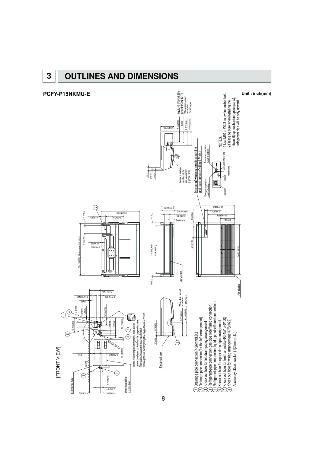
PCFY-P30NKMU-E, PCFY-P36NKMU-E, PCFY-P24NKMU-E, PCFY-P15NKMU-E specifications
Mitsubishi Electronics is renowned for its innovative solutions in the field of heating, ventilation, and air conditioning (HVAC) systems. Among its impressive lineup, the PCFY-P series of ceiling-mounted air conditioning units stands out for its advanced features, technologies, and efficient performance. The models PCFY-P15NKMU-E, PCFY-P24NKMU-E, PCFY-P36NKMU-E, and PCFY-P30NKMU-E cater to various cooling and heating needs, making them suitable for both residential and commercial applications.One of the main features of the PCFY-P series is its superior efficiency rating. With advanced inverter technology, these units provide precise temperature control by adjusting the compressor speed to match the cooling or heating demand. This not only leads to significant energy savings but also ensures a comfortable environment at all times.
Another notable characteristic of the PCFY-P series is its whisper-quiet operation. Designed with noise-reduction technologies, these models operate at sound levels as low as 19 dB, making them ideal for environments requiring minimal disturbance, such as offices, libraries, or bedrooms.
The multi-zone capability of the PCFY-P series enhances its versatility. Each model can connect to multiple indoor units, allowing users to customize their climate control across different zones in a building. This adaptability facilitates tailored cooling or heating solutions, optimizing comfort and energy use.
Mitsubishi's advanced filtration systems improve indoor air quality by removing dust, allergens, and microorganisms. The PCFY-P series is equipped with highly efficient filters, ensuring that the air circulated is clean and healthy.
Smart technology integration is another hallmark of these models. With built-in Wi-Fi capability, they can be remotely controlled through a smartphone app or accessed via various smart home systems. This feature allows users to adjust settings, monitor energy consumption, and schedule operation times conveniently.
Sustainability is a key focus in Mitsubishi's design philosophy. The PCFY-P series utilizes environmentally friendly refrigerants that have a low global warming potential, aligning with modern environmental regulations and initiatives.
In summary, the Mitsubishi Electronics PCFY-P15NKMU-E, PCFY-P24NKMU-E, PCFY-P36NKMU-E, and PCFY-P30NKMU-E offer exceptional efficiency, quiet operation, air quality improvement, smart technology integration, and sustainable design. These characteristics position the PCFY-P series as a leading choice in the HVAC market, providing reliable comfort solutions for a variety of settings. Each model exemplifies Mitsubishi's commitment to innovation and performance, making them a valuable asset for climate control needs.

