Front Panel
|
|
|
|
|
|
|
|
|
|
|
|
|
|
|
|
|
|
|
|
|
|
|
|
|
|
|
|
|
|
|
|
|
|
|
|
|
|
|
|
|
|
|
|
|
|
|
|
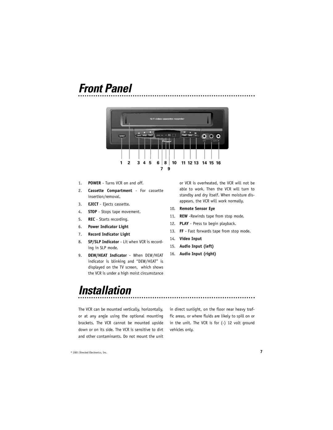
1 | 2 | 3 | 4 | 5 | 6 | 8 | 10 | 11 12 13 | 14 15 16 | ||||||
7 9
1.POWER - Turns VCR on and off.
2.Cassette Compartment - For cassette insertion/removal.
3.EJECT - Ejects cassette.
4.STOP - Stops tape movement.
5.REC - Starts recording.
6.Power Indicator Light
7.Record Indicator Light
8.SP/SLP Indicator - Lit when VCR is record- ing in SLP mode.
9.DEW/HEAT Indicator - When DEW/HEAT indicator is blinking and “DEW/HEAT” is displayed on the TV screen, which shows the VCR is under a high moist circumstance
or VCR is overheated, the VCR will not be able to work. Then the VCR will turn to standby and dry itself. When moisture dis- appears, the VCR will work normally.
10.Remote Sensor Eye
11.REW
12.PLAY - Press to begin playback.
13.FF - Fast forwards tape from stop mode.
14.Video Input
15.Audio Input (left)
16.Audio Input (right)
Installation
The VCR can be mounted vertically, horizontally, or at any angle using the optional mounting brackets. The VCR cannot be mounted upside down or on its side. The VCR is sensitive to dirt and other contaminants. Do not mount the unit
in direct sunlight, on the floor near heavy traf- fic areas, or where fluids are likely to spill on or in the unit. The VCR is for
© 2001 Directed Electronics, Inc. | 7 |