WIRING CONNECTIONS
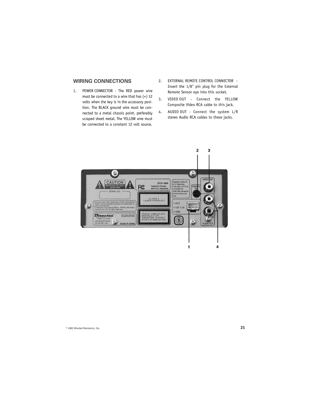
1.POWER CONNECTOR - The RED power wire must be connected to a wire that has (+) 12 volts when the key is in the accessory posi- tion. The BLACK ground wire must be con- nected to a metal chassis point, preferably scraped sheet metal. The YELLOW wire must be connected to a constant 12 volt source.
2.EXTERNAL REMOTE CONTROL CONNECTOR - Insert the 1/8" pin plug for the External Remote Sensor eye into this socket.
3.VIDEO OUT - Connect the YELLOW Composite Video RCA cable to this jack.
4.AUDIO OUT - Connect the system L/R stereo Audio RCA cables to these jacks.
2 3
14
© 2003 Directed Electronics, Inc. | 21 |