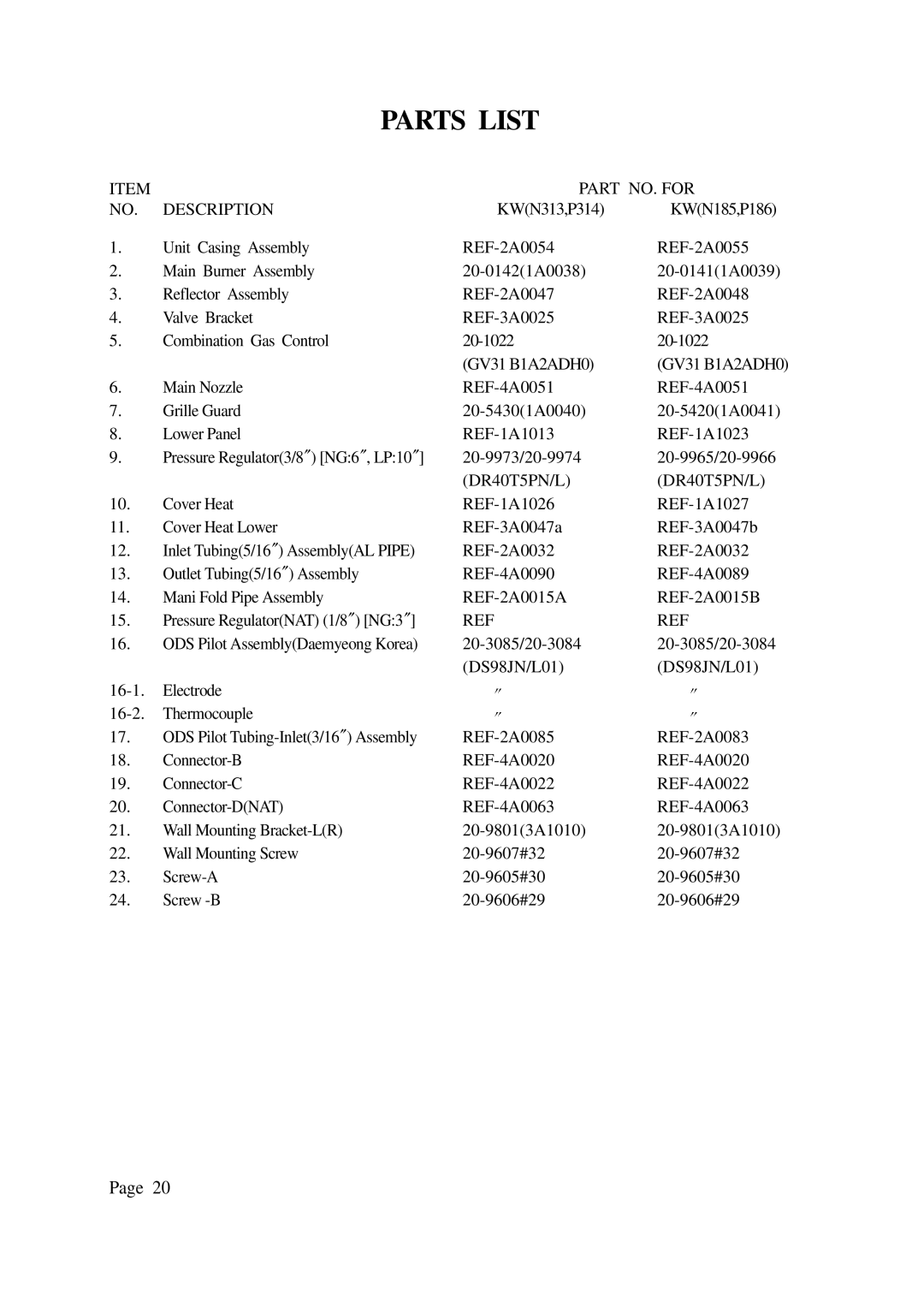
N313, N185, P186, P314 specifications
DreamGEAR has established itself as a leading brand in the gaming accessory market, offering products that enhance the gaming experience for both casual players and hardcore enthusiasts. Among its notable offerings are the DreamGEAR P186, N185, N313, and P314 models. Each of these products brings unique features and technologies tailored for gamers.The DreamGEAR P186 is a versatile gaming controller compatible with various platforms, including PC and consoles. One of its standout features is its ergonomic design that allows for comfortable prolonged gaming sessions. The controller incorporates advanced vibration feedback technology, providing players with a more immersive experience during gameplay. Its responsive buttons and customizable triggers enhance control and precision, allowing for an edge in competitive gaming. The P186 also supports programmable macros, enabling gamers to tailor controls to suit their personal playstyle.
Moving on to the DreamGEAR N185, this model is particularly designed for mobile gaming enthusiasts. It features a compact and portable design, making it easy to carry and use on the go. The N185 is compatible with a wide range of mobile devices and employs Bluetooth connectivity for a hassle-free gaming experience. The built-in rechargeable battery ensures extended gameplay while high-precision joysticks offer fluid control. Additionally, the N185 supports multiple gaming apps, allowing users to access their favorite titles seamlessly.
The DreamGEAR N313 is a complete gaming kit that caters to console gamers. This model includes a high-quality headset, charging station, and protective case, ensuring that every aspect of gaming is covered. The headset delivers immersive sound with its surround sound technology, making players feel as though they are part of the game. The charging station provides quick charging options and convenient cable management, while the protective case ensures that gaming gear stays safe during transport.
Finally, the DreamGEAR P314 offers a robust gaming experience with its built-in features for playback and streaming. This model is designed for gamers who want to create and share their gameplay moments. It comes equipped with a high-definition video capture option, allowing players to record and stream their sessions in crystal-clear quality. The P314 also integrates with popular streaming platforms, making it easy to share gameplay with a broad audience.
In summary, DreamGEAR's P186, N185, N313, and P314 models showcase the brand's commitment to innovation and quality, each designed to enhance the gaming experience through ergonomic design, cutting-edge technology, and user-friendly features. Whether for casual or professional use, these products cater to a multitude of gaming needs and preferences.