10.Rem ove charge if superheat is low and add charge if superheat is high.
|
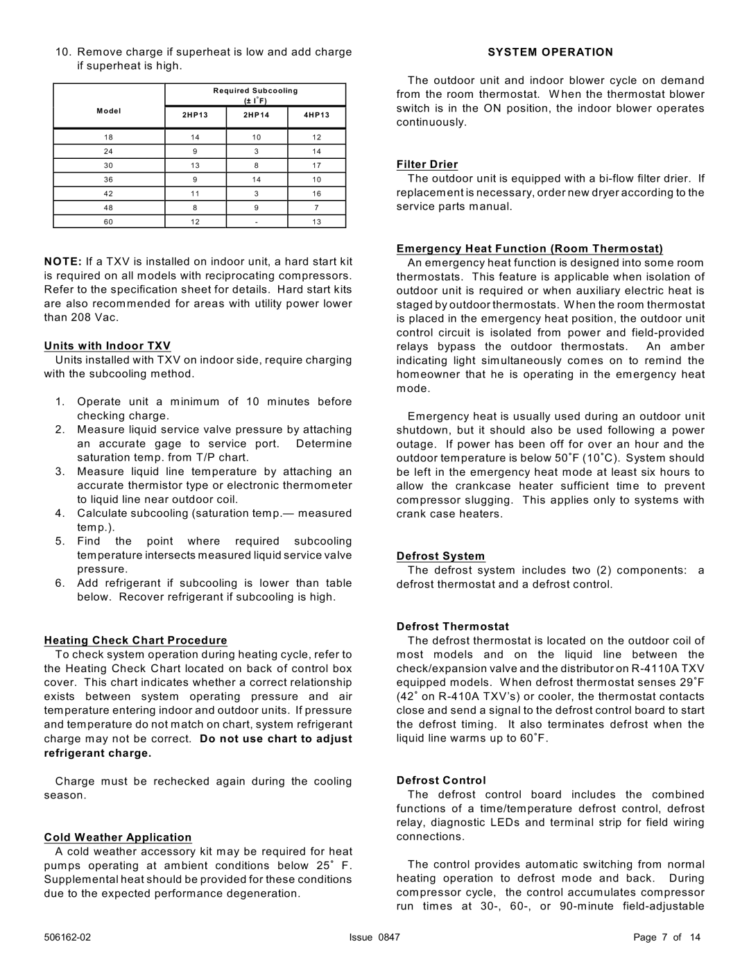
| Required Subcooling |
|
|
| (± I/F) |
|
M odel | 2HP13 | 2HP14 | 4HP13 |
| |||
1 8 | 1 4 | 1 0 | 1 2 |
2 4 | 9 | 3 | 1 4 |
3 0 | 1 3 | 8 | 1 7 |
3 6 | 9 | 1 4 | 1 0 |
4 2 | 1 1 | 3 | 1 6 |
4 8 | 8 | 9 | 7 |
6 0 | 1 2 | - | 1 3 |
NOTE: If a TXV is installed on indoor unit, a hard start kit is required on all models with reciprocating com pressors. Refer to the specification sheet for details. Hard start kits are also recomm ended for areas with utility power lower than 208 Vac.
Units with Indoor TXV
Units installed with TXV on indoor side, require charging with the subcooling method.
1.Operate unit a m inim um of 10 minutes before checking charge.
2.Measure liquid service valve pressure by attaching an accurate gage to service port. Determ ine saturation tem p. from T/P chart.
3.Measure liquid line tem perature by attaching an accurate therm istor type or electronic therm om eter to liquid line near outdoor coil.
4.Calculate subcooling (saturation tem p.— measured tem p.).
5. Find the point where required subcooling tem perature intersects measured liquid service valve pressure.
6.Add refrigerant if subcooling is lower than table below. Recover refrigerant if subcooling is high.
Heating Check Chart Procedure
To check system operation during heating cycle, refer to the Heating Check Chart located on back of control box cover. This chart indicates whether a correct relationship exists between system operating pressure and air tem perature entering indoor and outdoor units. If pressure and tem perature do not match on chart, system refrigerant charge may not be correct. Do not use chart to adjust
refrigerant charge.
Charge must be rechecked again during the cooling season.
Cold Weather Application
A cold weather accessory kit m ay be required for heat pumps operating at ambient conditions below 25/ F. Supplem ental heat should be provided for these conditions due to the expected perform ance degeneration.
SYSTEM OPERATION
The outdoor unit and indoor blower cycle on demand from the room therm ostat. W hen the therm ostat blower switch is in the ON position, the indoor blower operates continuously.
Filter Drier
The outdoor unit is equipped with a
Emergency Heat Function (Room Thermostat)
An emergency heat function is designed into some room therm ostats. This feature is applicable when isolation of outdoor unit is required or when auxiliary electric heat is staged by outdoor therm ostats. W hen the room therm ostat is placed in the em ergency heat position, the outdoor unit control circuit is isolated from power and
Em ergency heat is usually used during an outdoor unit shutdown, but it should also be used following a power outage. If power has been off for over an hour and the outdoor tem perature is below 50/F (10/C). System should be left in the em ergency heat mode at least six hours to allow the crankcase heater sufficient tim e to prevent com pressor slugging. This applies only to system s with crank case heaters.
Defrost System
The defrost system includes two (2) com ponents: a defrost therm ostat and a defrost control.
Defrost Thermostat
The defrost therm ostat is located on the outdoor coil of m ost models and on the liquid line between the check/expansion valve and the distributor on
Defrost Control
The defrost control board includes the com bined functions of a tim e/tem perature defrost control, defrost relay, diagnostic LEDs and term inal strip for field wiring connections.
The control provides autom atic switching from norm al heating operation to defrost mode and back. During com pressor cycle, the control accumulates compressor run tim es at
Issue 0847 | Page 7 of 14 |