Elevate Unit
Accum ulation of water and ice in base pan m ay cause equipm ent damage.
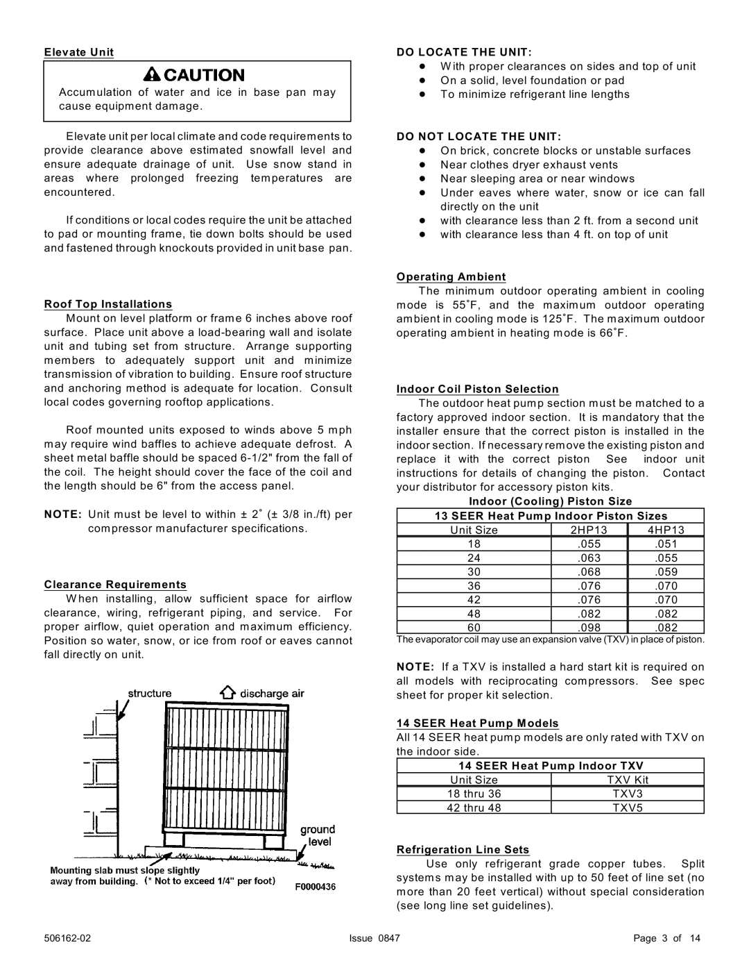
Elevate unit per local clim ate and code requirem ents to provide clearance above estim ated snowfall level and ensure adequate drainage of unit. Use snow stand in areas where prolonged freezing tem peratures are encountered.
If conditions or local codes require the unit be attached to pad or mounting fram e, tie down bolts should be used and fastened through knockouts provided in unit base pan.
Roof Top Installations
Mount on level platform or fram e 6 inches above roof surface. Place unit above a
Roof mounted units exposed to winds above 5 m ph m ay require wind baffles to achieve adequate defrost. A sheet m etal baffle should be spaced
NOTE: Unit m ust be level to within ± 2/ (± 3/8 in./ft) per
com pressor manufacturer specifications.
Clearance Requirements
W hen installing, allow sufficient space for airflow clearance, wiring, refrigerant piping, and service. For proper airflow, quiet operation and maxim um efficiency. Position so water, snow, or ice from roof or eaves cannot fall directly on unit.
DO LOCATE THE UNIT:
!W ith proper clearances on sides and top of unit
!On a solid, level foundation or pad
!To minim ize refrigerant line lengths
DO NOT LOCATE THE UNIT:
!On brick, concrete blocks or unstable surfaces
!Near clothes dryer exhaust vents
!Near sleeping area or near windows
!Under eaves where water, snow or ice can fall directly on the unit
!with clearance less than 2 ft. from a second unit
!with clearance less than 4 ft. on top of unit
Operating Ambient
The minim um outdoor operating am bient in cooling m ode is 55/F, and the maxim um outdoor operating am bient in cooling mode is 125/F. The m axim um outdoor operating am bient in heating mode is 66/F.
Indoor Coil Piston Selection
The outdoor heat pum p section m ust be m atched to a factory approved indoor section. It is m andatory that the installer ensure that the correct piston is installed in the indoor section. If necessary rem ove the existing piston and replace it with the correct piston See indoor unit instructions for details of changing the piston. Contact your distributor for accessory piston kits.
Indoor (Cooling) Piston Size
13 SEER Heat Pump Indoor Piston Sizes
Unit Size | 2HP13 | 4HP13 |
18 | .055 | .051 |
24 | .063 | .055 |
30 | .068 | .059 |
36 | .076 | .070 |
42 | .076 | .070 |
48 | .082 | .082 |
60 | .098 | .082 |
The evaporator coil may use an expansion valve (TXV) in place of piston.
NOTE: If a TXV is installed a hard start kit is required on all models with reciprocating com pressors. See spec sheet for proper kit selection.
14 SEER Heat Pump Models
All 14 SEER heat pum p m odels are only rated with TXV on the indoor side.
14 SEER Heat Pump Indoor TXV
Unit Size | TXV Kit |
18 thru 36 | TXV3 |
42 thru 48 | TXV5 |
Refrigeration Line Sets
Use only refrigerant grade copper tubes. Split system s may be installed with up to 50 feet of line set (no m ore than 20 feet vertical) without special consideration (see long line set guidelines).
Issue 0847 | Page 3 of 14 |