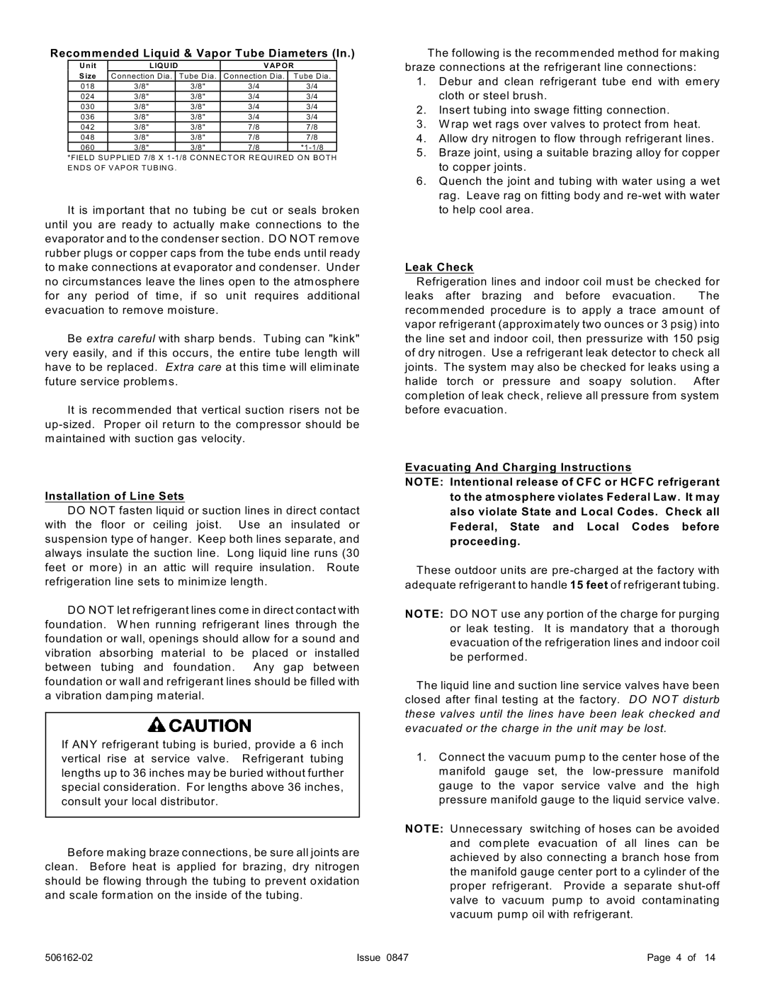
Recommended Liquid & Vapor Tube Diameters (In.)
Unit | LIQ UID |
| VAPO R | |
Size | C o n ne c tion D ia . | Tube Dia . | C onnection D ia . | Tube Dia . |
018 | 3/8" | 3/8" | 3/4 | 3/4 |
024 | 3/8" | 3/8" | 3/4 | 3/4 |
030 | 3/8" | 3/8" | 3/4 | 3/4 |
036 | 3/8" | 3/8" | 3/4 | 3/4 |
042 | 3/8" | 3/8" | 7/8 | 7/8 |
048 | 3/8" | 3/8" | 7/8 | 7/8 |
060 | 3/8" | 3/8" | 7/8 | |
*FIELD SUPP LIED 7/8 X 1
It is im portant that no tubing be cut or seals broken until you are ready to actually make connections to the evaporator and to the condenser section. DO NOT rem ove rubber plugs or copper caps from the tube ends until ready to make connections at evaporator and condenser. Under no circum stances leave the lines open to the atm osphere for any period of tim e, if so unit requires additional evacuation to rem ove moisture.
Be extra careful with sharp bends. Tubing can "kink" very easily, and if this occurs, the entire tube length will have to be replaced. Extra care at this tim e will elim inate future service problem s.
It is recomm ended that vertical suction risers not be
Installation of Line Sets
DO NOT fasten liquid or suction lines in direct contact with the floor or ceiling joist. Use an insulated or suspension type of hanger. Keep both lines separate, and always insulate the suction line. Long liquid line runs (30 feet or m ore) in an attic will require insulation. Route refrigeration line sets to minim ize length.
DO NOT let refrigerant lines com e in direct contact with foundation. W hen running refrigerant lines through the foundation or wall, openings should allow for a sound and vibration absorbing material to be placed or installed between tubing and foundation. Any gap between foundation or wall and refrigerant lines should be filled with a vibration dam ping material.
If ANY refrigerant tubing is buried, provide a 6 inch vertical rise at service valve. Refrigerant tubing lengths up to 36 inches m ay be buried without further special consideration. For lengths above 36 inches, consult your local distributor.
Before m aking braze connections, be sure all joints are clean. Before heat is applied for brazing, dry nitrogen should be flowing through the tubing to prevent oxidation and scale form ation on the inside of the tubing.
The following is the recomm ended method for making braze connections at the refrigerant line connections:
1.Debur and clean refrigerant tube end with em ery cloth or steel brush.
2.Insert tubing into swage fitting connection.
3.W rap wet rags over valves to protect from heat.
4.Allow dry nitrogen to flow through refrigerant lines.
5.Braze joint, using a suitable brazing alloy for copper to copper joints.
6.Quench the joint and tubing with water using a wet rag. Leave rag on fitting body and
Leak Check
Refrigeration lines and indoor coil m ust be checked for
leaks after brazing and before evacuation. The recomm ended procedure is to apply a trace am ount of vapor refrigerant (approxim ately two ounces or 3 psig) into the line set and indoor coil, then pressurize with 150 psig of dry nitrogen. Use a refrigerant leak detector to check all joints. The system m ay also be checked for leaks using a halide torch or pressure and soapy solution. After com pletion of leak check, relieve all pressure from system before evacuation.
Evacuating And Charging Instructions
NOTE: Intentional release of CFC or HCFC refrigerant to the atmosphere violates Federal Law . It may also violate State and Local Codes. Check all Federal, State and Local Codes before proceeding.
These outdoor units are
NOTE: DO NOT use any portion of the charge for purging or leak testing. It is mandatory that a thorough evacuation of the refrigeration lines and indoor coil be perform ed.
The liquid line and suction line service valves have been closed after final testing at the factory. DO NOT disturb these valves until the lines have been leak checked and evacuated or the charge in the unit may be lost.
1.Connect the vacuum pump to the center hose of the m anifold gauge set, the
NOTE: Unnecessary switching of hoses can be avoided and com plete evacuation of all lines can be achieved by also connecting a branch hose from the manifold gauge center port to a cylinder of the proper refrigerant. Provide a separate
Issue 0847 | Page 4 of 14 |