Manuals
/
Ducane (HVAC)
/
Household Appliance
/
Heat Pump
Ducane (HVAC)
2HP13/14
warranty
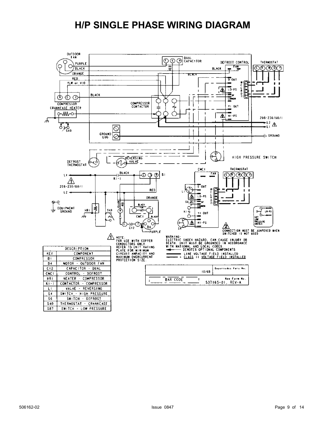
Single Phase Wiring Diagram
Models:
2HP13/14
1
9
14
14
Download
14 pages
11.88 Kb
6
7
8
9
10
11
12
13
Install
Single Phase Wiring Diagram
Time Delay
Control Wiring
Start-Up Procedure
Page 9
Image 9
H/P SINGLE PHASE WIRING DIAGRAM
506162-02
Issue 0847
Page 9 of 14
Page 8
Page 10
Page 9
Image 9
Page 8
Page 10
Contents
Table of Contents
Unit Location & Installation
Install on a Solid, Level Mounting Pad
Outdoor Section
Do not Locate the Unit
Do Locate the Unit
Recommended Liquid & Vapor Tube Diameters
Installation of Line Sets
Leak Check
Evacuating And Charging Instructions
Install Electrical Accessories
Opening Service Valves
Control Wiring
Electrical Connections
Adjusting Charge
Start-Up Procedure
Refrigeration Charge Adjustment
Emergency Heat heating heat pump
System Operation
Pressure Switch Circuit
Time Delay
Diagnostic Leds
Defrost Control board Diagnostic LED
Single Phase Wiring Diagram
3 Phase Wiring Diagram
Failure to do SO could Result in Bodily Injury or Death
Important System Information
Regular Maintenance Requirements
Air Filter
Indoor Coil
Allied AIR Enterprises Equipment Limited Warranty
Issue
Top
Page
Image
Contents