INSTALLATION

Installation of the Projector and Screen

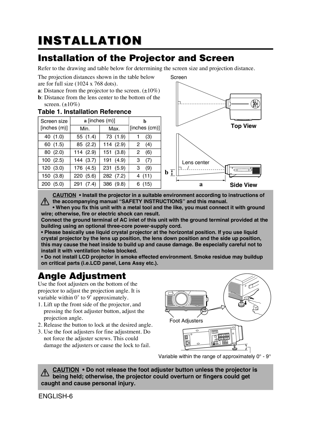
Refer to the drawing and table below for determining the screen size and projection distance.

The projection distances shown in the table below are for full size (1024 x 768 dots).

a: Distance from the projector to the screen. (±10%)

b: Distance from the lens center to the bottom of the screen. (±10%)

Table 1. Installation Reference

Screen size


a [inches (m)]


b

[inches (m)]


[inches (cm)]

Min.

Max.


40

(1.0)

55

(1.4)

73

(1.9)

1

(3)


60

(1.5)

85

(2.2)

114

(2.9)

2

(4)


80

(2.0)

114

(2.9)

151

(3.8)

2

(6)


100

(2.5)

144

(3.7)

191

(4.9)

3

(7)


120

(3.0)

176

(4.5)

231

(5.9)

3

(9)


150

(3.8)

220

(5.6)

282

(7.2)

4

(11)


200

(5.0)

291

(7.4)

386

(9.8)

6

(15)


Screen

Top View

Lens center

b

aSide View

CAUTION • Install the projector in a suitable environment according to instructions of the accompanying manual “SAFETY INSTRUCTIONS” and this manual.

When you fix this unit with a metal tool and the like, you must connect it with ground wire; otherwise, fire or electric shock can result.

Connect the ground terminal of AC inlet of this unit with the ground terminal provided at the building using an optional three-core power-supply cord.

Please basically use liquid crystal projector at the horizontal position. If you use liquid crystal projector by the lens up position, the lens down position and the side up position, this may cause the heat inside to build up and cause damage. Be especially careful not to install it with ventilation holes blocked.

Do not install LCD projector in smoke effected environment. Smoke residue may buildup on critical parts (i.e.LCD panel, Lens Assy etc.).

Angle Adjustment

Use the foot adjusters on the bottom of the projector to adjust the projection angle. It is variable within 0˚ to 9˚ approximately.

1.Lift up the front side of the projector, and pressing the foot adjuster button, adjust the projection angle.

2.Release the button to lock at the desired angle.

3.Use the foot adjusters for fine adjustment. Do not force the adjuster screws. This could damage the adjusters or cause the lock to fail.

Foot Adjusters

Variable within the range of approximately 0° - 9°

CAUTION • Do not release the foot adjuster button unless the projector is being held; otherwise, the projector could overturn or fingers could get

caught and cause personal injury.

ENGLISH-6

Page 8
Image 8
Dukane 8941A, 28A8941 user manual Installation of the Projector and Screen, Angle Adjustment, Installation Reference

28A8941, 8941A specifications

The Dukane 8941A and 28A8941 are advanced ultrasonic welding systems designed for high-performance applications across a variety of industries. These machines exemplify the cutting-edge technology that Dukane has to offer, making them vital tools for manufacturers seeking reliable and efficient joining solutions.

One of the standout features of the Dukane 8941A and 28A8941 is their ultrasonic technology, which utilizes high-frequency vibration to create localized heating at the interface of materials. This process allows for quick and efficient joining of thermoplastics, metals, and other materials with minimal pressure and without the need for adhesives or fasteners. The systems operate at frequencies typically around 20 kHz, which optimizes the welding process by ensuring fast cycle times and consistent, repeatable results.

The systems come equipped with an intuitive user interface, making it easy for operators to set parameters and monitor the welding process in real-time. This user-friendly design helps minimize the learning curve and allows for efficient operation in various production environments. Additionally, the machines provide comprehensive data logging capabilities, enabling users to track performance metrics and maintain quality control with ease.

Another significant characteristic of the Dukane 8941A and 28A8941 is their adaptability. These ultrasonic welding systems can be tailored to accommodate different applications, whether the need is for spot welding, staking, or cutting. The machines can also handle a wide range of material thicknesses, ensuring versatility in manufacturing processes.

In terms of durability and maintenance, Dukane has designed these systems with robust components that are engineered for prolonged use. Regular maintenance is made simple, allowing manufacturers to keep their equipment running smoothly with minimal downtime.

Moreover, the Dukane 8941A and 28A8941 incorporate advanced safety features, ensuring that operators can work without risk. The systems include emergency stop buttons, overload protection, and built-in fail-safes, prioritizing both performance and operator security.

In summary, the Dukane 8941A and 28A8941 ultrasonic welding systems represent a pinnacle of modern manufacturing technology. With their efficient ultrasonic technology, user-friendly interfaces, adaptability to various applications, durability, and integrated safety features, these machines stand out as premier solutions for businesses looking to enhance their production capabilities.