TECHNICAL

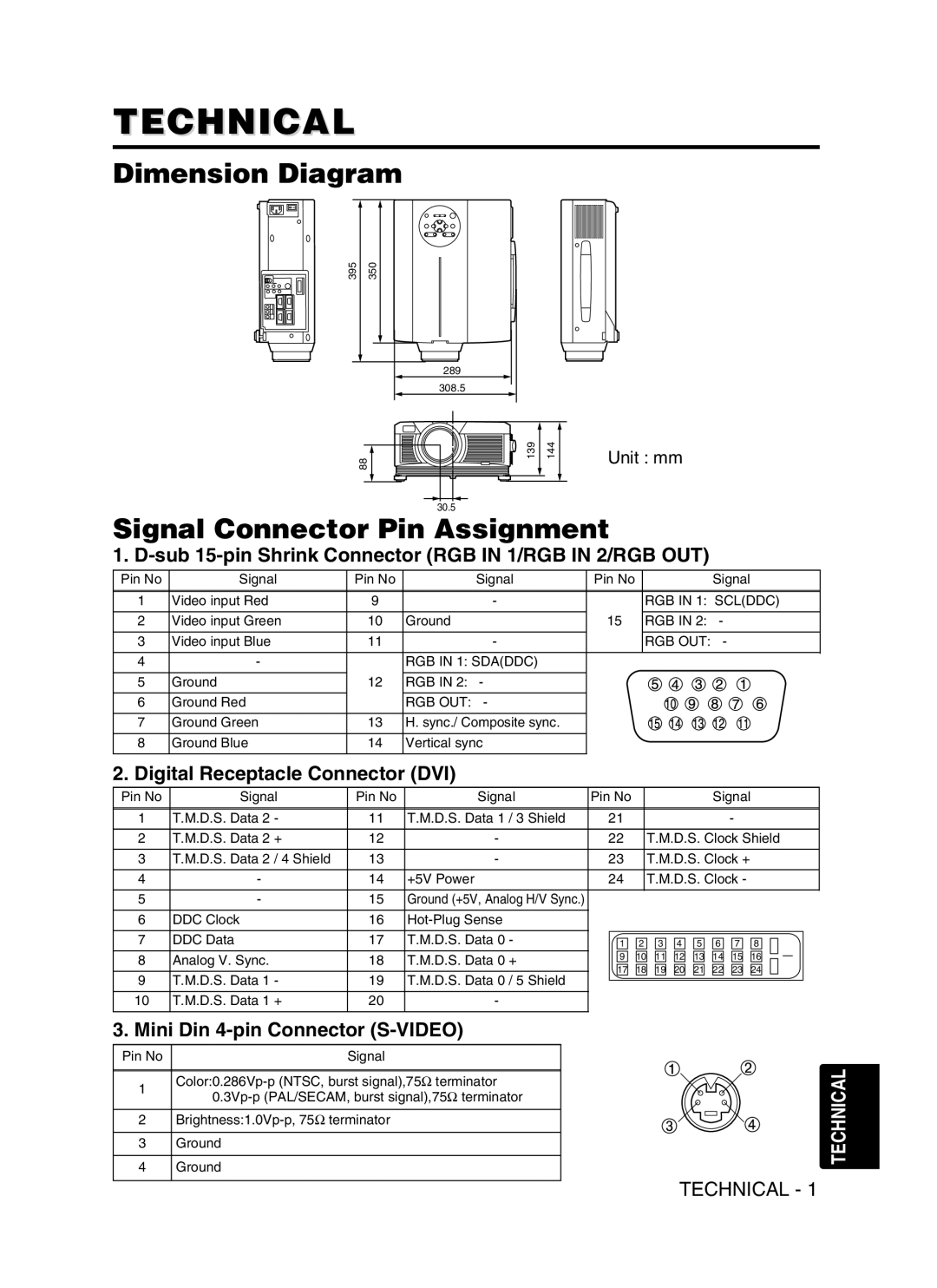
Dimension Diagram

395

350


289


308.5


88

139

144

Unit : mm


30.5


Signal Connector Pin Assignment

1. D-sub 15-pin Shrink Connector (RGB IN 1/RGB IN 2/RGB OUT)

Pin No

Signal

Pin No


Signal

Pin No


Signal


1

Video input Red

9


-


RGB IN 1: SCL(DDC)


2

Video input Green

10


Ground

15


RGB IN 2:

-


3

Video input Blue

11


-


RGB OUT:

-


4

-


RGB IN 1: SDA(DDC)


10

9

8

7

6


5

Ground

12


RGB IN 2: -


6

Ground Red


RGB OUT: -


15

14

13

12

11


7

Ground Green

13


H. sync./ Composite sync.


8

Ground Blue

14


Vertical sync


2. Digital Receptacle Connector (DVI)


Pin No

Signal

Pin No

Signal

Pin No


Signal


1

T.M.D.S. Data 2 -

11


T.M.D.S. Data 1 / 3 Shield

21


-


2

T.M.D.S. Data 2 +

12


-


22


T.M.D.S. Clock Shield


3

T.M.D.S. Data 2 / 4 Shield

13


-


23


T.M.D.S. Clock +


4

-

14


+5V Power

24


T.M.D.S. Clock -


5

-

15


Ground (+5V, Analog H/V Sync.)


6

DDC Clock

16


Hot-Plug Sense


7

DDC Data

17


T.M.D.S. Data 0 -

1

2

3

4

5

6

7

8


8

Analog V. Sync.

18


T.M.D.S. Data 0 +

9

10

11

12

13

14

15

16


17

18

19

20

21

22

23

24


9

T.M.D.S. Data 1 -

19


T.M.D.S. Data 0 / 5 Shield


10

T.M.D.S. Data 1 +

20


-


3. Mini Din 4-pin Connector (S-VIDEO)


Pin No


Signal


Color:0.286Vp-p (NTSC, burst signal),75terminator

10.3Vp-p (PAL/SECAM, burst signal),75terminator

2Brightness:1.0Vp-p, 75terminator

3Ground

4Ground

TECHNICAL

TECHNICAL - 1

Page 27
Image 27
Dukane 28A8941, 8941A user manual Technical, Dimension Diagram, Signal Connector Pin Assignment

28A8941, 8941A specifications

The Dukane 8941A and 28A8941 are advanced ultrasonic welding systems designed for high-performance applications across a variety of industries. These machines exemplify the cutting-edge technology that Dukane has to offer, making them vital tools for manufacturers seeking reliable and efficient joining solutions.

One of the standout features of the Dukane 8941A and 28A8941 is their ultrasonic technology, which utilizes high-frequency vibration to create localized heating at the interface of materials. This process allows for quick and efficient joining of thermoplastics, metals, and other materials with minimal pressure and without the need for adhesives or fasteners. The systems operate at frequencies typically around 20 kHz, which optimizes the welding process by ensuring fast cycle times and consistent, repeatable results.

The systems come equipped with an intuitive user interface, making it easy for operators to set parameters and monitor the welding process in real-time. This user-friendly design helps minimize the learning curve and allows for efficient operation in various production environments. Additionally, the machines provide comprehensive data logging capabilities, enabling users to track performance metrics and maintain quality control with ease.

Another significant characteristic of the Dukane 8941A and 28A8941 is their adaptability. These ultrasonic welding systems can be tailored to accommodate different applications, whether the need is for spot welding, staking, or cutting. The machines can also handle a wide range of material thicknesses, ensuring versatility in manufacturing processes.

In terms of durability and maintenance, Dukane has designed these systems with robust components that are engineered for prolonged use. Regular maintenance is made simple, allowing manufacturers to keep their equipment running smoothly with minimal downtime.

Moreover, the Dukane 8941A and 28A8941 incorporate advanced safety features, ensuring that operators can work without risk. The systems include emergency stop buttons, overload protection, and built-in fail-safes, prioritizing both performance and operator security.

In summary, the Dukane 8941A and 28A8941 ultrasonic welding systems represent a pinnacle of modern manufacturing technology. With their efficient ultrasonic technology, user-friendly interfaces, adaptability to various applications, durability, and integrated safety features, these machines stand out as premier solutions for businesses looking to enhance their production capabilities.