December 2004
Operating Mechanisms with Disconnect Switches | 25 | |
– Variable Depth | ||
|
Technical Data and Specifications
Datum
A ![]()
![]() D
D ![]() E
E ![]()
![]() F
F ![]()
![]()
![]() Datum
Datum
C
G
1.62 ![]()
![]() (41.1)
(41.1)
.62Min.
(15.7)
B
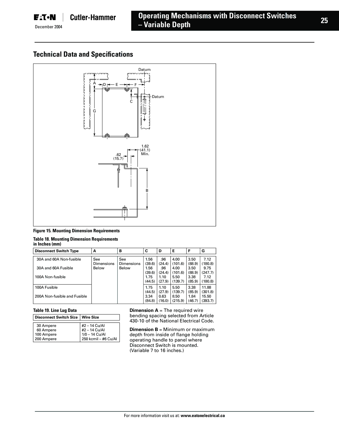
Figure 15. Mounting Dimension Requirements
Table 18. Mounting Dimension Requirements
in Inches (mm)
Disconnect Switch Type | A | B | C | D | E | F | G |
|
|
|
|
|
|
|
|
|
|
|
|
|
|
|
|
30A and 60A | See | See | 1.56 | .96 | 4.00 | 3.50 | 7.12 |
30A and 60A Fusible | Dimensions | Dimensions | (39.6) | (24.4) | (101.6) | (88.9) | (180.8) |
Below | Below | 1.56 | .96 | 4.00 | 3.50 | 9.75 | |
100A |
|
| (39.6) | (24.4) | (101.6) | (88.9) | (247.7) |
|
| 1.75 | 1.10 | 5.50 | 3.38 | 7.12 | |
|
|
| (44.5) | (27.9) | (139.7) | (85.9) | (180.8) |
100A Fusible |
|
| 1.75 | 1.10 | 5.50 | 3.38 | 11.88 |
200A |
|
| (44.5) | (27.9) | (139.7) | (85.9) | (301.8) |
|
| 3.34 | 0.63 | 8.50 | 1.84 | 15.50 | |
|
|
| (84.8) | (16.0) | (215.9) | (46.7) | (393.7) |
|
|
|
|
|
|
|
|
Table 19. Line Lug Data
Disconnect Switch Size | Wire Size |
|
|
|
|
30 Ampere | #2 – 14 Cu/Al |
60 Ampere | #2 – 14 Cu/Al |
100 Ampere | 1/0 – 14 Cu/Al |
200 Ampere | 250 kcmil – #6 Cu/Al |
|
|
Dimension A = The required wire bending spacing selected from Article
Dimension B = Minimum or maximum depth from inside of flange holding operating handle to panel where Disconnect Switch is mounted. (Variable 7 to 16 inches.)
For more information visit us at: www.eatonelectrical.ca