December 2004
Circuit Breaker Operating Mechanisms
Flange – Variable Depth, Flange Mounted – Fixed Depth | 29 |
|
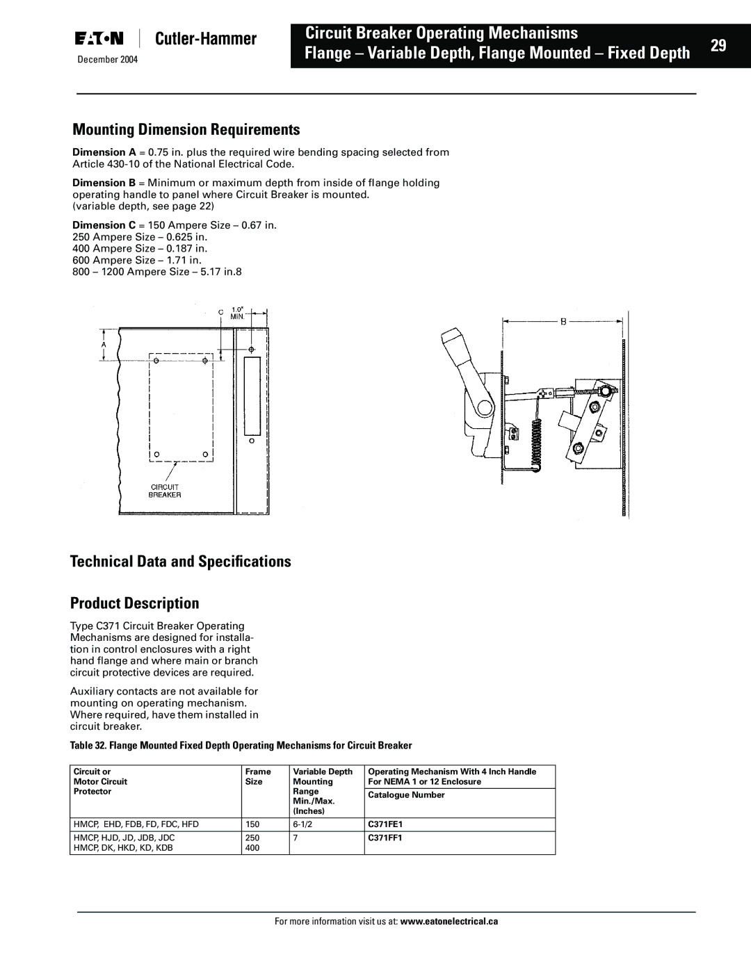
Mounting Dimension Requirements
Dimension A = 0.75 in. plus the required wire bending spacing selected from Article
Dimension B = Minimum or maximum depth from inside of flange holding operating handle to panel where Circuit Breaker is mounted.
(variable depth, see page 22)
Dimension C = 150 Ampere Size – 0.67 in. 250 Ampere Size – 0.625 in.
400 Ampere Size – 0.187 in.
600 Ampere Size – 1.71 in.
800 – 1200 Ampere Size – 5.17 in.8
Technical Data and Specifications
Product Description
Type C371 Circuit Breaker Operating Mechanisms are designed for installa- tion in control enclosures with a right hand flange and where main or branch circuit protective devices are required.
Auxiliary contacts are not available for mounting on operating mechanism. Where required, have them installed in circuit breaker.
Table 32. Flange Mounted Fixed Depth Operating Mechanisms for Circuit Breaker
Circuit or | Frame | Variable Depth | Operating Mechanism With 4 Inch Handle |
Motor Circuit | Size | Mounting | For NEMA 1 or 12 Enclosure |
Protector |
| Range |
|
| Catalogue Number | ||
|
| Min./Max. | |
|
|
| |
|
| (Inches) |
|
|
|
|
|
HMCP, EHD, FDB, FD, FDC, HFD | 150 | C371FE1 | |
|
|
|
|
HMCP, HJD, JD, JDB, JDC | 250 | 7 | C371FF1 |
HMCP, DK, HKD, KD, KDB | 400 |
|
|
|
|
|
|
For more information visit us at: www.eatonelectrical.ca