28 | Circuit Breaker Operating Mechanisms | |
Flange Mounted – Fixed Depth | ||
|
December 2004
|
|
|
| Product Description | ||
|
|
|
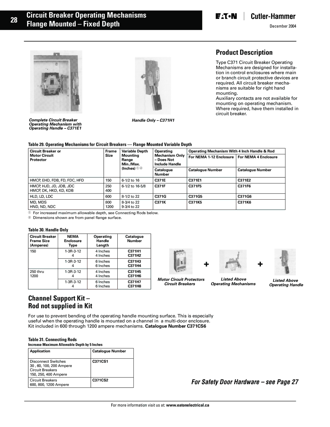
| Type C371 Circuit Breaker Operating | ||
|
|
|
| Mechanisms are designed for installa- | ||
|
|
|
| tion in control enclosures where main | ||
|
|
|
| or branch circuit protective devices are | ||
|
|
|
| required. All circuit breaker mecha- | ||
|
|
|
| nisms are suitable for right hand | ||
|
|
|
| mounting. | ||
|
|
|
| Auxiliary contacts are not available for | ||
|
|
|
| mounting on operating mechanism. | ||
|
|
|
| Where required, have them installed in | ||
|
|
|
| circuit breaker. | ||
Complete Circuit Breaker |
| Handle Only – C371H1 |
|
|
| |
Operating Mechanism with |
|
|
|
|
|
|
Operating Handle – C371E1 |
|
|
|
|
|
|
Table 29. Operating Mechanisms for Circuit Breakers — Flange Mounted Variable Depth |
|
| ||||
|
|
|
|
|
|
|
Circuit Breaker or | Frame | Variable Depth | Operating | Operating Mechanism With 4 Inch Handle & Rod |
| |
Motor Circuit | Size | Mounting | Mechanism Only |
|
|
|
For NEMA | For NEMA 4 Enclosure |
| ||||
Protector |
| Range | – Does Not |
| ||
|
|
|
| |||
|
| Min./Max. | Include Handle |
|
|
|
|
| (Inches) |
|
|
|
|
|
| Catalogue | Catalogue Number | Catalogue Number |
| |
|
|
|
| |||
|
|
| Number |
|
|
|
|
|
|
|
|
|
|
HMCP, EHD, FDB, FD, FDC, HFD | 150 | C371E | C371E1 | C371E2 |
| |
|
|
|
|
|
|
|
HMCP, HJD, JD, JDB, JDC | 250 | C371F | C371F5 | C371F6 |
| |
HMCP, DK, HKD, KD, KDB | 400 |
|
|
|
|
|
HLD, LD, LDC | 600 | C371G | C371G5 | C371G6 |
| |
|
|
|
|
|
|
|
MD, MDS | 800 | C371K | C371K5 | C371K6 |
| |
HND, ND, NDC | 1200 |
|
|
|
|
|
For increased maximum allowable depth, see Connecting Rods below.
Dimensions shown are from panel flange surface.
Table 30. Handle Only
Circuit Breaker | NEMA | Operating | Catalogue |
|
|
|
Frame Size | Enclosure | Handle | Number |
|
|
|
(Amperes) | Type | Length |
|
|
|
|
|
|
|
|
|
|
|
150 | 4 Inches | C371H1 |
|
|
| |
| 4 | 4 Inches | C371H2 | + |
| + |
|
|
|
|
| ||
| 6 Inches | C371H3 |
| |||
| 4 | 6 Inches | C371H4 |
| ||
250 thru | 4 Inches | C371H5 |
|
|
| |
1200 | 4 | 4 Inches | C371H6 | Motor Circuit Protectors | Listed Above | Listed Above |
|
|
|
| |||
| 6 Inches | C371H7 | ||||
| Circuit Breakers | Operating Mechanisms | Operating Handle | |||
| 4 | 6 Inches | C371H8 | |||
|
|
|
| |||
|
|
|
|
|
|
|
Channel Support Kit –
Rod not supplied in Kit
For use to prevent bending of the operating handle mounting surface. This is especially useful when the operating handle is mounted on a channel in a
Table 31. Connecting Rods
Increase Maximum Allowable Depth by 5 Inches
Application | Catalogue Number |
|
|
Disconnect Switches | C371CS1 |
30 , 60, 100, 200 Ampere |
|
Circuit Breakers |
|
150, 250, 400 Ampere |
|
|
|
Circuit Breakers | C371CS2 |
600, 800, 1200 Ampere |
|
For Safety Door Hardware – see Page 27
For more information visit us at: www.eatonelectrical.ca
