2.5 Probe Compensation
Before taking measurements with the USBscope50, the attached x10 scope probe must be compensated to ensure that it is matched to the scope input stage8.
This ensures that the probe+scope act together to keep the input frequency response as flat as possible. Using a scope probe that has not been adjusted to match the USBscope50 can lead to inaccurate readings for higher frequency signals.
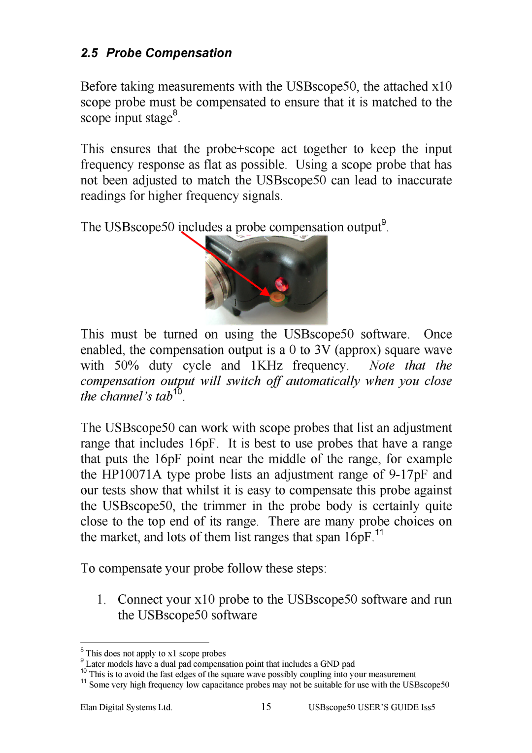
The USBscope50 includes a probe compensation output9.
This must be turned on using the USBscope50 software. Once enabled, the compensation output is a 0 to 3V (approx) square wave with 50% duty cycle and 1KHz frequency. Note that the compensation output will switch off automatically when you close the channel’s tab10.
The USBscope50 can work with scope probes that list an adjustment range that includes 16pF. It is best to use probes that have a range that puts the 16pF point near the middle of the range, for example the HP10071A type probe lists an adjustment range of
To compensate your probe follow these steps:
1.Connect your x10 probe to the USBscope50 software and run the USBscope50 software
8This does not apply to x1 scope probes
9Later models have a dual pad compensation point that includes a GND pad
10This is to avoid the fast edges of the square wave possibly coupling into your measurement
11Some very high frequency low capacitance probes may not be suitable for use with the USBscope50
Elan Digital Systems Ltd. | 15 | USBscope50 USER’S GUIDE Iss5 |
