Control and Functions
Overall Layout
1
8
7
Operation Guide
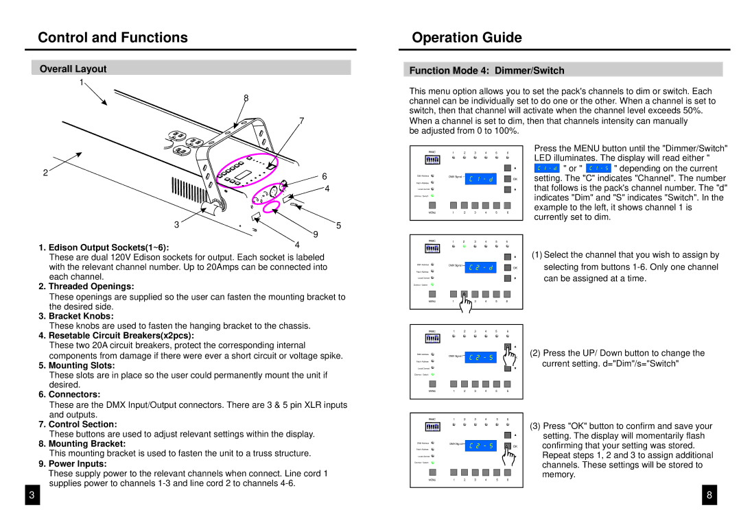
Function Mode 4: Dimmer/Switch
This menu option allows you to set the pack's channels to dim or switch. Each channel can be individually set to do one or the other. When a channel is set to switch, then that channel will activate when the channel level exceeds 50%.
When a channel is set to dim, then that channels intensity can manually be adjusted from 0 to 100%.
2 | 6 |
| |
| 4 |
3 | 5 |
| 9 |
1. Edison Output Sockets(1~6): | 4 |
These are dual 120V Edison sockets for output. Each socket is labeled with the relevant channel number. Up to 20Amps can be connected into each channel.
2. Threaded Openings: |
These openings are supplied so the user can fasten the mounting bracket to |
PANIC | 1 | 2 | 3 | 4 | 5 | 6 |
ON | MD | |
1 | 2 3 | 4 5 6 |
DMX Address | DMX Signal |
OK
Patch Address
Local Control
Dimmer / Switch
MENU | 1 | 2 | 3 | 4 | 5 | 6 |
PANIC | 1 | 2 | 3 | 4 | 5 | 6 |
ON | MD | |
1 | 2 3 4 | 5 6 |
DMX Address | DMX Signal |
OK
Patch Address
Local Control
Dimmer / Switch
Press the MENU button until the "Dimmer/Switch" LED illuminates. The display will read either "
![]()
![]()
![]()
![]()
![]()
![]()
![]()
![]()
![]() " or "
" or " ![]()
![]()
![]()
![]()

![]()
![]()
![]() " depending on the current setting. The "C" indicates "Channel". The number that follows is the pack's channel number. The "d" indicates "Dim" and "S" indicates "Switch". In the example to the left, it shows channel 1 is currently set to dim.
" depending on the current setting. The "C" indicates "Channel". The number that follows is the pack's channel number. The "d" indicates "Dim" and "S" indicates "Switch". In the example to the left, it shows channel 1 is currently set to dim.
(1)Select the channel that you wish to assign by selecting from buttons
| the desired side. |
3. | Bracket Knobs: |
| These knobs are used to fasten the hanging bracket to the chassis. |
4. | Resetable Circuit Breakers(x2pcs): |
| These two 20A circuit breakers, protect the corresponding internal |
| components from damage if there were ever a short circuit or voltage spike. |
5. | Mounting Slots: |
| These slots are in place so the user could permanently mount the unit if |
| desired. |
6. | Connectors: |
| These are the DMX Input/Output connectors. There are 3 & 5 pin XLR inputs |
| and outputs. |
MENU | 1 |
| 3 | 4 | 5 | 6 |
PANIC | 1 | 2 | 3 | 4 | 5 | 6 |
ON | MD |
1 2 3 | 4 5 6 |
DMX Address | DMX Signal |
|
|
|
| (2) Press the UP/ Down button to change the |
|
|
|
| |||
Patch Address |
|
|
|
|
| current setting. d="Dim"/s="Switch" |
Local Control |
|
|
|
|
|
|
Dimmer / Switch |
|
|
|
|
|
|
MENU | 1 | 2 | 3 | 4 | 5 | 6 |
PANIC | 1 | 2 | 3 | 4 | 5 | 6 |
7. | Control Section: |
| These buttons are used to adjust relevant settings within the display. |
8. | Mounting Bracket: |
| This mounting bracket is used to fasten the unit to a truss structure. |
9. | Power Inputs: |
| These supply power to the relevant channels when connect. Line cord 1 |
ON | MD |
1 2 3 | 4 5 6 |
DMX Address | DMX Signal |
Patch Address
Local Control
Dimmer / Switch
| (3) Press "OK" button to confirm and save your |
| setting. The display will momentarily flash |
OK | confirming that your setting was stored. |
| Repeat steps 1, 2 and 3 to assign additional |
| channels. These settings will be stored to |
| memory. |
supplies power to channels |
3
MENU | 1 | 2 | 3 | 4 | 5 | 6 |
8